Wireless sensor network time synchronization method and device based on error statistics

A wireless sensor, time synchronization technology, applied in the communication between multiple stations, data exchange through path configuration, advanced technology, etc., can solve the problems of low synchronization accuracy, large synchronization process complexity, and large number of exchanged messages. , to achieve the effect of good synchronization accuracy and energy consumption, good adaptability and high scalability

Inactive Publication Date: 2007-12-12
INST OF SOFTWARE - CHINESE ACAD OF SCI
View PDF0 Cites 34 Cited by
  • Summary
  • Abstract
  • Description
  • Claims
  • Application Information

AI Technical Summary

Problems solved by technology

Although the RBS time synchronization method eliminates the synchronization error introduced by the propagation delay of the sending end and improves the synchronization accuracy, this method is only suitable for small-scale networks, has poor scalability, and has a large number of exchanged messages; the DMTS time synchronization method has low complexity. It is easy to expand to a large-scale network, but the compensation for message propagation delay is a fixed value, which cannot adapt to changes in network deployment, and the synchronization accuracy is relatively low; the TPSN time synchronization method introduces the NTP time synchronization method into the wireless sensor network. A better accuracy has been achieved, but the complexity of the synchronization process is relatively large, the number of messages exchanged is large, and the convergence speed is slow
Specifically, the estimation of the error introduced by the propagation delay by the above method cannot actually reflect the overall delay of the network

Method used


Image

  • Wireless sensor network time synchronization method and device based on error statistics
  • Wireless sensor network time synchronization method and device based on error statistics
  • Wireless sensor network time synchronization method and device based on error statistics

Examples


Embodiment Construction

[0035] specific implementation plan

[0036] The present invention will be described in detail below with reference to the accompanying drawings and examples.

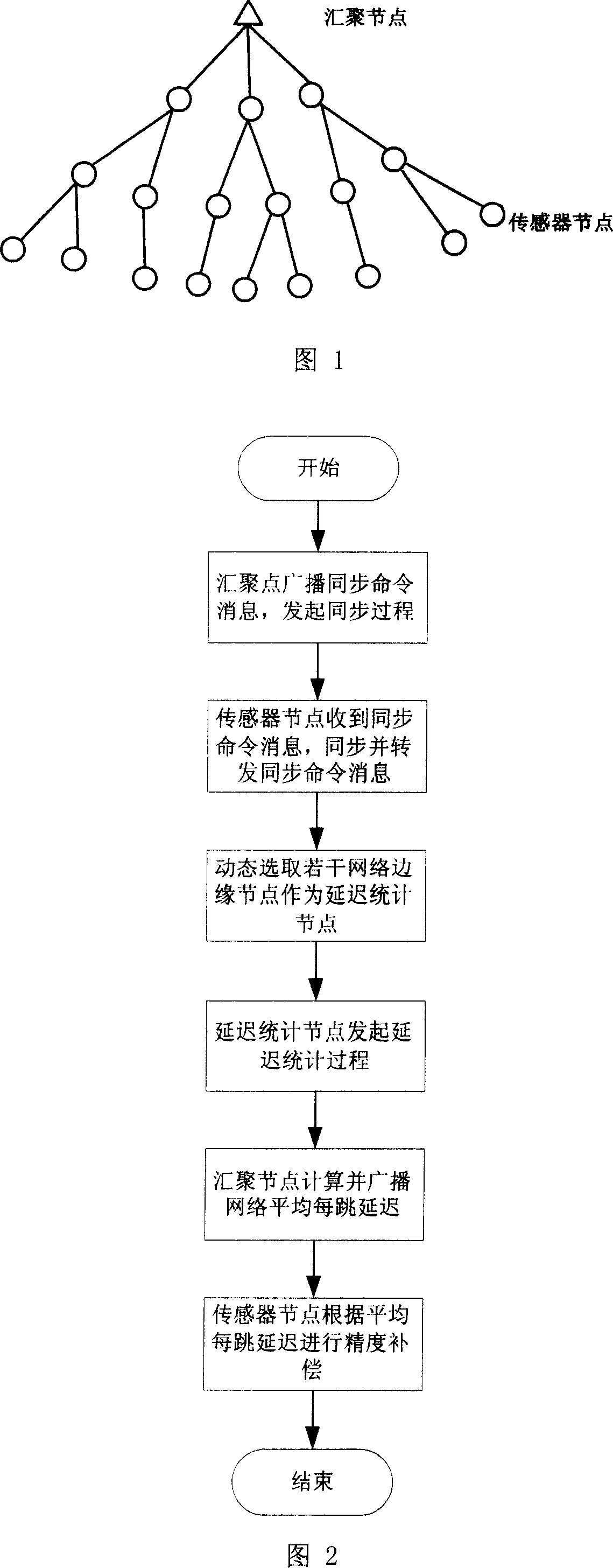
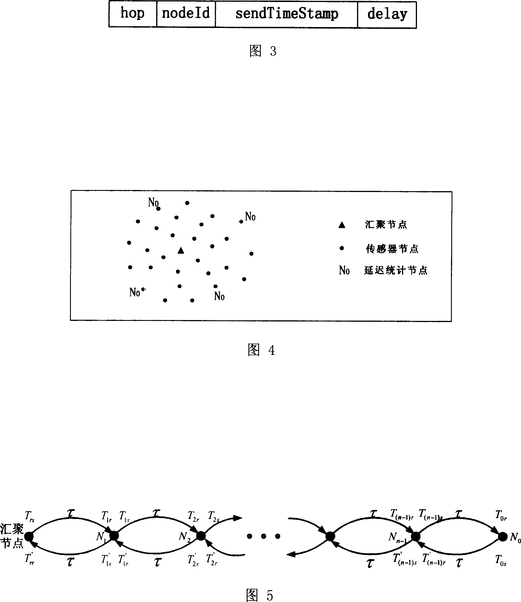
[0037] The flow of the ESTS time synchronization method is shown in Figure 2. The convergence node broadcasts a synchronization command message through its time synchronization start module to start the time synchronization process. The message format of the synchronization command is shown in Figure 3, where hop represents the number of hops between the node sending the message and the sink node; nodeId is the node number sending the message; sendTimeStamp is the timestamp added when sending the message, indicating that the node sending the message The local time of the node when the message specifies the byte; delay records the cumulative propagation delay during the synchronization process, and is initialized to 0;

[0038]After the neighbor node (sensor node) of the sink node receives the synchronization command m...


PUM


Abstract

A synchronies method of wireless sensor network time based on error statistics includes steps: uses the flood course of synchronous command message to reach the time synchronism with low accuracy in short time, and build network tree hierarchical structure at same time; dynamic choosing part or whole edge nodes of network are the delay statistical node; statistical synchronizes message is from concourse nodes to delay statistical node, and delay statistical message is from delay statistical node to concourse node; calculates the transmission delay of every jump; compensate the synchronizing accuracy according to transmission delay of every jump and the jump number of concourse node to reach the time synchronism with high accuracy, which is used in wireless transmission network, containing concourse node and sensor node, and all nodes are tree structure whose root nodes are concourse node. The method has good adaptability, extension, and high synchronism accuracy, and it has good split between synchronism accuracy and power consumption.

Description

technical field [0001] The invention relates to a time synchronization technology in a wireless sensor network, in particular to a time synchronization method and device for a wireless sensor network based on error statistics. Background technique [0002] Wireless sensor network is a multi-hop wireless network system composed of a large number of sensor nodes in a self-organizing manner. Its purpose is to cooperatively sense, collect, process and transmit the monitoring information of sensing objects in the network coverage area, and report to users. Wireless sensor network integrates sensing technology, embedded technology, wireless network technology, distributed intelligent information processing and other technologies. It has the characteristics of large scale, low cost and flexible networking. It has been widely used in military, scientific research, industrial monitoring, medical and other fields. [0003] Time synchronization is one of the basic functions of wireles...

Claims


Application Information

Patent Timeline
Patent Type & Authority Applications(China)
IPC IPC(8): H04L12/28H04B7/26
CPCY02D30/70
Inventor 孙利民王海东何庆伟柯欣
Owner INST OF SOFTWARE - CHINESE ACAD OF SCI
Why Eureka
Try Eureka