Radiation module and its heat pipe

A heat dissipation module and heat pipe technology, applied in indirect heat exchangers, lighting and heating equipment, cooling/ventilation/heating transformation, etc., can solve the problems of affecting the quality of the working fluid of the heat pipe 10, high cost, and high cost of parts processing

Active Publication Date: 2007-12-19
DELTA ELECTRONICS INC
View PDF0 Cites 9 Cited by
  • Summary
  • Abstract
  • Description
  • Claims
  • Application Information

AI Technical Summary

Problems solved by technology

[0005] However, the heat pipe body 12 is usually processed by forging, which not only has high processing costs, but also has a high scrap rate (generally exceeding 50%), resulting in high processing costs for the parts.
In addition, the combination of the heat pipe body 12 and the upper cover 14, and the combination of the upper cover 14 and the water injection pipe 18 all need to be welded with filler solder, and the cost is also high, thereby affecting the competitiveness and profit of the overall product.
[0006] In addition, for the columnar heat pipe 10 using the capillary structures 16a, 16b produced by powder sintering, due to the limitations of factors such as sintering molds and manufacturing processes, the capillary structure 16b on the bottom 124 and the capillary structure 16a on the side wall 122 It is sintered by filling powder together, but there is usually no additional capillary structure on the inner surface of the upper cover 14, so that the working fluid condensed at the upper cover 14 cannot return, causing the upper cover 14 to become an invalid condensation end, which affects Changes in the quality of the working fluid in the heat pipe 10 affect the heat transfer efficiency and overall thermal resistance of the heat pipe 10

Method used


Image

  • Radiation module and its heat pipe
  • Radiation module and its heat pipe
  • Radiation module and its heat pipe

Examples


Embodiment Construction

[0044] Embodiments of the heat dissipation module and the heat pipe thereof of the present invention will be described below with reference to related drawings.

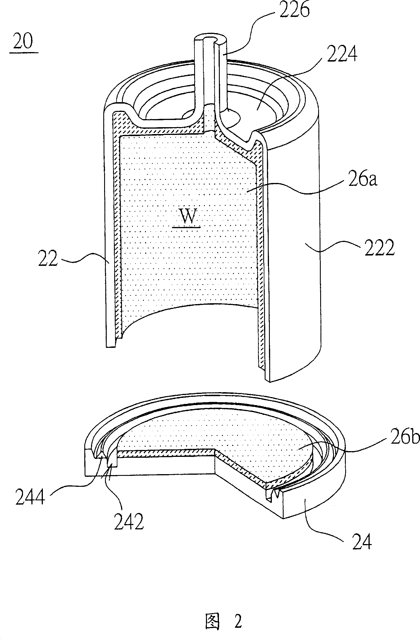
[0045]Please refer to FIG. 2 , which is a schematic diagram of a columnar heat pipe according to a preferred embodiment of the present invention. The cylindrical heat pipe 20 of the present invention includes a heat pipe body 22 and a base 24 . The heat pipe body 22 has a top 224 and a side wall 222 surrounding the top 224 . The side wall 222 and the top 224 are integrally formed. The side wall 222 of the heat pipe body 22 is hollow columnar. The top 224 of the heat pipe body 22 protrudes outwards and is integrally formed with a water injection pipe 226 , and the base 24 is opposite to the top 224 of the heat pipe body 22 .

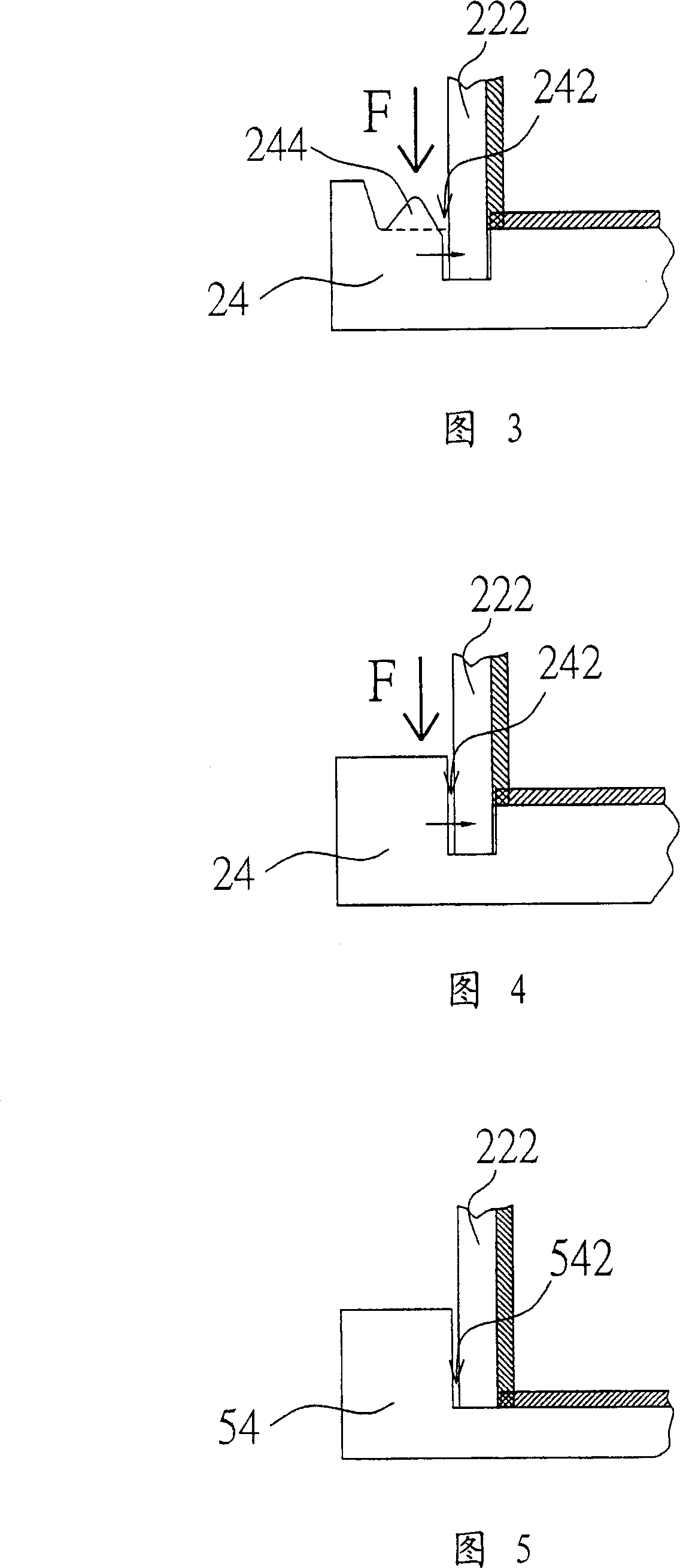
[0046] Please refer to FIGS. 2-4 at the same time. FIGS. 3 and 4 are schematic cross-sectional views of the heat pipe body 22 and the base 24 shown in FIG. 2 before and after assembly. In FIG....


PUM


Abstract

A heat-sink module is prepared as setting heat -sink fin at external of heat pipe and connecting the two with each other, forming heat pipe body by unified top unit and side wall being set around said top unit, setting base with ring-shaped groove to be opposite to said unified top unit and enabling to insert side wall of heat pipe body into ring-shaped groove of base for jointing said base with heat pipe body firmly.

Description

technical field [0001] The invention relates to a heat dissipation module, in particular to a heat dissipation module with a heat pipe which is easy to process and saves manufacturing cost. Background technique [0002] With the advancement of technology, the number of transistors per unit area of ​​electronic components is increasing, resulting in an increase in heat generation during operation. On the other hand, the operating frequency of electronic components is also getting higher and higher, and the heat (switch loss) caused by the on / off (on / off) conversion during transistor operation is also the reason for the increase in the heat generation of electronic components. If the heat is not properly handled, the computing speed of the chip will be reduced, and in severe cases, the life of the chip may even be affected. In order to enhance the heat dissipation effect of electronic components, most of the current methods use radiators to dissipate the heat at the heat sour...

Claims


Application Information

Patent Timeline
Patent Type & Authority Applications(China)
IPC IPC(8): F28D15/02H05K7/20
Inventor 游明辉林棋逢陈锦明
Owner DELTA ELECTRONICS INC
Why Eureka
Try Eureka