Supercharge Your Innovation With Domain-Expert AI Agents!

A wind turbine blade equipped internally with collection means

A technology of wind power generators and collection devices, applied in the field of blades, can solve problems such as endangering the surrounding environment

Active Publication Date: 2010-09-29
LM GLASSFIBER
View PDF3 Cites 0 Cited by
  • Summary
  • Abstract
  • Description
  • Claims
  • Application Information

AI Technical Summary

Problems solved by technology

In addition, it is also possible to prevent the drain hole from being blocked, thereby eliminating the need for maintenance on the drain hole; at the same time, the problem of endangering the surrounding environment due to loose objects thrown outside through the blade drain hole is also solved.

Method used


Image

  • A wind turbine blade equipped internally with collection means
  • A wind turbine blade equipped internally with collection means
  • A wind turbine blade equipped internally with collection means

Examples


Embodiment Construction

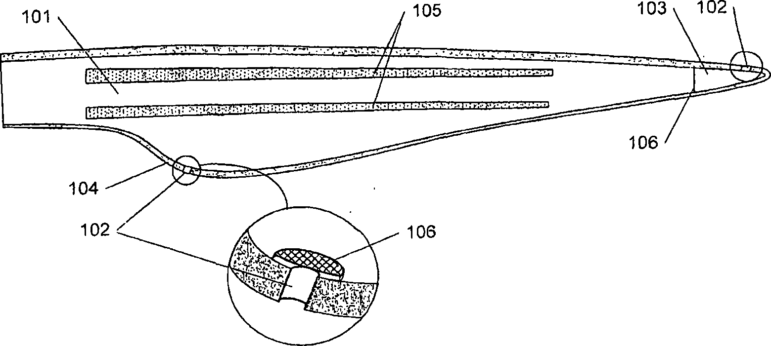
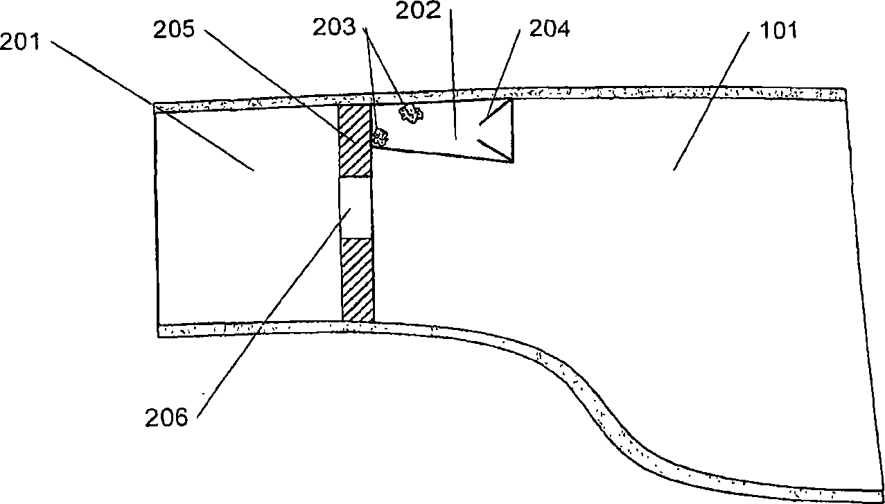
[0026] figure 1 is a cross-sectional view of a blade 101 for a wind generator. Typically a blade is assembled from two blade shells and some internal support struts 105 so that the blade comprises one or more cavities. In order to also allow moisture to flow out of the blade when in use, a plurality of drainage holes 102 are provided on the blade. In the example given, said weep holes 102 are provided at the tip 103 of the blade, and at the right rear of the outermost part of the rear edge 104 of the blade. According to an embodiment of the present invention, a plurality of filters 106 are arranged inside the blade 101 . Advantageously, they are located in front of each drain hole 102, so that objects or particles larger than the mesh of the filter cannot enter into the drain holes 102 and accordingly do not block the drain holes. Smaller particles either pass through or are captured by the filter. According to another embodiment of the invention, the filter is arranged to...


PUM


Abstract

The invention relates to a blade for a wind power plant composed of at least two blade parts, whereby the blade comprises a cavity, wherein the cavity is provided with means for collecting e.g. dust, particles or loose objects from the cavity. Such collection means comprise containers with funnel-shaped openings, with a flap or with adhesive o the inner side. The collection means may moreover be a kind of filter or sieves arranged between chambers interiorly of the blade.

Description

technical field [0001] The invention relates to a blade for a wind power generator, said blade consisting of at least two blade parts, said blade comprising a cavity. Background technique [0002] A blade is usually constructed of two or more blade sections, shells or blade halves of reinforced fiber sheets bonded to each other or to one or more internal support columns. One or more cavities are thereby formed in such blades. When gluing the blade parts to each other, enough glue or filler is used to ensure that the glue joints are filled. Excess glue that thickens around the glue joints or falls into the mold is scraped off and moved as far as possible; but inevitably, a considerable amount of glue remains on the blade on the blade, especially where the glue remains on the outermost and narrowest part of the blade. As the blade is used, the blade dynamically bends and deforms, so the glue at the glue seam will fall off as a lump and fall inside the blade. Theoretically,...

Claims


Application Information

Patent Timeline
Patent Type & Authority Patents(China)
IPC IPC(8): F03D1/06F01D5/18F03D11/00B64C27/473
CPCY02E10/722F03D11/0016Y02E10/721F05B2260/63F03D80/55Y02E10/72
Inventor M·莫尔岑K·L·马森R·范登贝尔赫
Owner LM GLASSFIBER
Features
  • R&D
  • Intellectual Property
  • Life Sciences
  • Materials
  • Tech Scout
  • Unparalleled Data Quality
  • Higher Quality Content
  • 60% Fewer Hallucinations
Learn More