Gravity drive pump of microflow controlled chip system

A microfluidic chip, gravity-driven technology, applied in the direction of analyzing materials, instruments, etc., can solve the problems of reduced flow rate, fluid-driven pressure drop, etc., to achieve the effect of constant flow rate

Inactive Publication Date: 2007-12-26
SHANDONG NORMAL UNIV
View PDF0 Cites 7 Cited by
  • Summary
  • Abstract
  • Description
  • Claims
  • Application Information

AI Technical Summary

Problems solved by technology

[0003] The gravity pump adopts the natural gravity field of the earth and does not require an additional power source. It is the prefer

Method used


Image

  • Gravity drive pump of microflow controlled chip system
  • Gravity drive pump of microflow controlled chip system

Examples


Embodiment 1

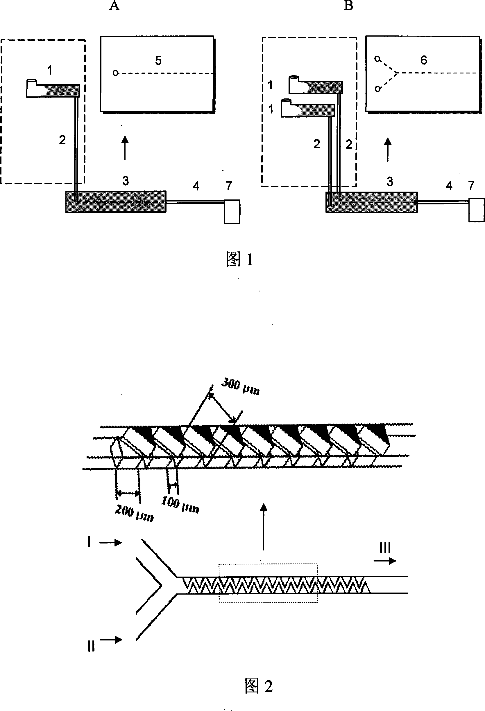
[0025] As shown in Fig. 1A, it is a constant flow gravity-driven pump of the microfluidic chip system provided by the present invention. It is composed of a liquid reservoir 1 placed horizontally, a connecting conduit 2, a microfluidic chip 3 with a single microchannel and a flow rate regulating tube 4 connected in sequence. The volume of the reservoir 1 is 500 microliters, placed horizontally; the connecting conduit 2 is a PEEK tube with an inner diameter of 254 microns and an outer diameter of 1.6 mm; the equivalent inner diameter of the microfluidic chip 3 is 300 microns, and the length is 2 cm channel chip; the flow rate is adjusted Tube 4 is a 3 cm long plastic catheter with an inner diameter of 100 microns and an outer diameter of 1.6 mm. The driving fluid is deionized water, and 7 is an outlet reservoir. The microfluidic chip 3 is made of PDMS material and a crocodile-tooth-shaped mixing channel. The chip has two inlets (I, II) opening up to accept the fluid from the r...

Embodiment 2

[0027] Fig. 1B is a microfluidic chip system provided by the present invention with constant flow and gravity double pumps. Dual reservoirs and channel chips enable binary drive operation. It is composed of two horizontally placed liquid reservoirs 1, two connecting conduits 2, a microfluidic chip 3 with a Y-shaped microchannel and a flow rate regulating tube 4 connected in sequence. The dimensions of the microfluidic chip of the Y-shaped microchannel are shown in Figure 2. The dimensions of other corresponding components are the same as in Example 1, and the driving fluid is deoxyribonucleic acid (DNA) solution of 16mer single-stranded labeled TAMRA and TET. The flow rate was 634 nL / min. Other microfluidic chips 3 and flow rate regulating tubes 4 are the same as in Embodiment 1.


PUM

PropertyMeasurementUnit
The inside diameter ofaaaaaaaaaa

Abstract

A gravity driving-pump of micro-flow control chip system is prepared for using multiple liquid storage pools as liquid storage pool in said pump, connecting fluid flow-rate regulation pipe to needle valve and switch, laying said liquid storage pool with internal diameter of 2-6mm and length of 5-10 times as internal diameter horizontally, using non-hydrophily polymerized material guide tube with internal diameter of 0.1-0.3mm as connection guide tube.

Description

Technical field: [0001] The invention relates to a constant-flow gravity pump of a microfluidic chip system, in particular to a constant-flow gravity-driven micropump for a microanalysis system. Background technique: [0002] Since the microfluidic chip system appeared in the 1990s, it has gradually shown its importance and broad application prospects in the research and application of life sciences, pharmacy and chemistry. Microfluidic chip systems usually require one or more pumps to drive fluid through microchannels to accomplish a specific task. At present, there are many kinds of fluid driving methods commonly used, mainly including the following categories: mechanical pump driving method, especially the use of micro and small mechanical pumps, such as micro-flow syringe pumps; non-mechanical pump driving methods, such as electric hydraulic pumps, Electroosmotic pumps, thermal capillary pumps and conventional gravity pumps, etc. The above-mentioned pumps have their ow...

Claims


Application Information

Patent Timeline
IPC IPC(8): G01N35/00G01N35/10
Inventor 李清岭陈令新唐波
Owner SHANDONG NORMAL UNIV
Why Eureka
Try Eureka