

Electronic equipment and method of manufacturing the electronic equipment
一种电子设备、连接设备的技术,应用在接触件盒/底座的制造、电路、电气元件等方向,能够解决连接可靠性下降、应力残留等问题,达到防止连接可靠性降低的效果
Inactive Publication Date: 2007-12-26
OMRON AUTOMOTIVE ELECTRONICS CO LTD
View PDF2 Cites 10 Cited by
- Summary
- Abstract
- Description
- Claims
- Application Information
AI Technical Summary
Problems solved by technology
[0006] However, in a conventional structure such as Patent Document 1, since the cover accommodated in the housing and the connector exposed from the housing are integrated, the attachment and detachment of the connector on the opposite side is relatively difficult for the connector. Or the impact of foreign objects, etc., when an external force is applied to the connector, the external force is directly transmitted from the connector to the cover, and the welding connection between the cover and the control substrate and the metal substrate is subject to stress, and the welding is destroyed, which will reduce the reliability of the connection. decline
In addition, in the conventional structure of Patent Document 2, since the connector is fixed on the housing with screws and the terminals of the connector are welded to the control board inside the housing, there may be problems due to dimensional errors or assembly errors of the parts, etc. On the other hand, when an external force is applied to the connector, stress is applied to the solder connection portion between the terminal of the connector and the control substrate, and the stress remains, and furthermore, the stress is applied to the solder connection portion of the control substrate, the high-current substrate, and the metal substrate, and the stress remains. This soldering gradually breaks down over time, making the connection less reliable
In addition, in the conventional structures of Patent Documents 1 and 2, when an external force is applied to the connector due to poor thermal shrinkage characteristics of the materials of each component, stress is applied to the cover, the substrate, or the solder connection portion of the connector. The solder is damaged, which will reduce the reliability of the connection
Method used
View moreImage
Smart ImageViewing Examples

Examples
Embodiment Construction
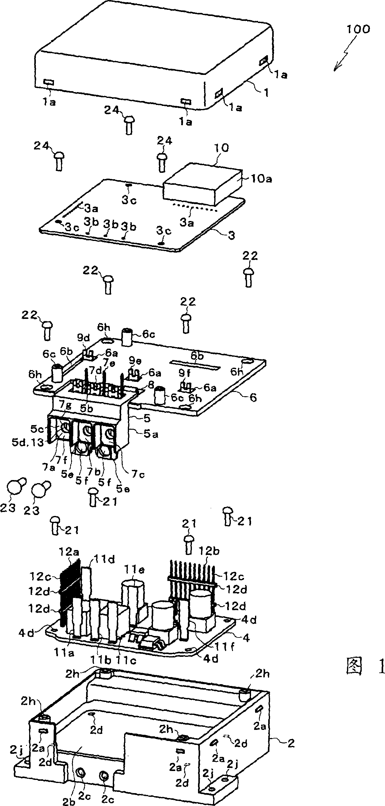
[0053] FIG. 1 is an exploded view of an electronic device 100 according to an embodiment of the present invention. The electronic device 100 is an electronic control device (also referred to as ECU: Electronic Control Unit) of an electric power steering device mounted on an automobile. The electric power steering system is composed of the electronic device 100 and a three-phase motor 90 (shown in FIG. 12 ) that generates a steering assist torque corresponding to the operation of a handle with respect to a steering shaft of an automobile (not shown). The electronic device 100 is mechanically and electrically connected to the motor 90 and controls the driving of the motor 90 .
Login to View More PUM
 Abstract
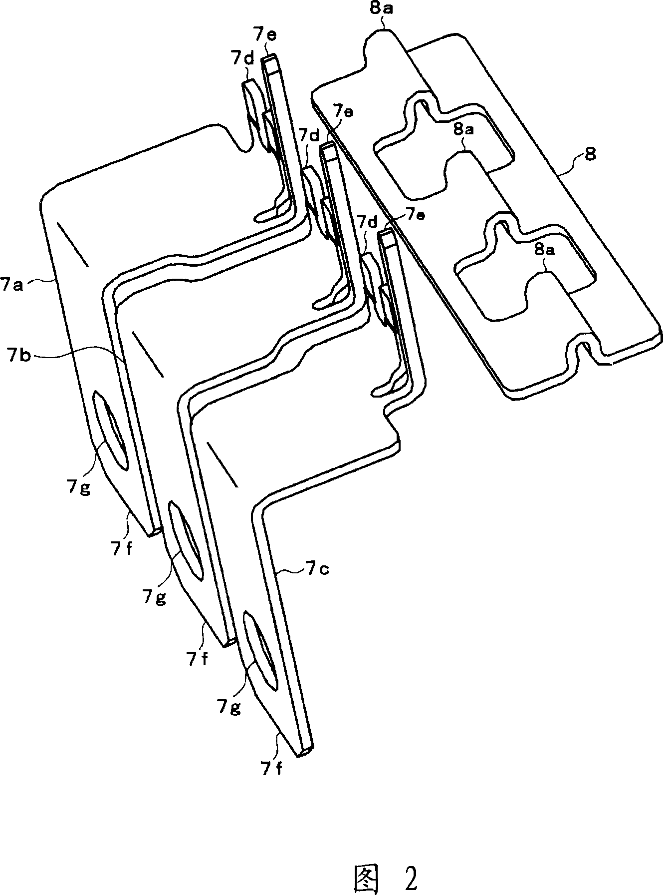
To prevent lowering of connection reliability of soldering connection portions of electronic equipment, there is provided electronic equipment which is equipped with a connector electrically connected to an electric motor, a control board and a power module board to which the connectors and other electric parts are electrically connected by soldering, a base for supporting the boards and the connector while overlapped with the boards and cases for fixing the connector while the connector is exposed from an opening portion, and fixing the boards while the boards and the base are accommodated in the cases. The connector is supported by the base through a beam as a flexible metal piece.
Description
technical field [0001] The present invention relates to electronic equipment with connectors for electrically connecting connected equipment. Background technique [0002] As an electronic device with a connector, there is, for example, an electronic control device (also referred to as ECU: Electronic Control Unit: electric control unit) of an electric power steering device mounted on a motor vehicle disclosed in Patent Documents 1 and 2 below. The electronic control unit is connected to the motor by screws or the like, and is electrically connected via a connector. The electronic control unit controls the driving of the electric motor to generate a steering assist torque corresponding to the handle operation with respect to the steering shaft. [0003] In Patent Document 1, a conductive plate is insert-molded in an insulating resin, a cover and a connector are integrally formed, the cover, a control board, and a metal board are stacked and electrically connected by welding...
Claims
Login to View More Application Information
Patent Timeline
 Patent Type & AuthorityApplications(China)
IPC IPC(8): H01R13/40B62D5/04
CPCH01R13/73Y10T29/49002H01R43/18H01R13/6315H01R43/24H01R2201/26H01R13/405
Inventor安田武史长岛笃史
OwnerOMRON AUTOMOTIVE ELECTRONICS CO LTD