Finger joint steel wire coupled transmission mechanism for robot clever hand finger

A technology of transmission mechanism and dexterous hand, applied in the directions of manipulators, chucks, manufacturing tools, etc., can solve the problems of poor movement coordination, inconvenient preloading, complex structure, etc., and achieve smooth movement, convenient preloading, and good movement coordination. Effect

Inactive Publication Date: 2008-01-09
HARBIN INST OF TECH
View PDF0 Cites 37 Cited by
  • Summary
  • Abstract
  • Description
  • Claims
  • Application Information

AI Technical Summary

Problems solved by technology

[0003] In order to solve the problems of complex structure, inconvenient pre-tightening, poor reliability, and poor movement coordination when fingers are bent in the

Method used


Image

  • Finger joint steel wire coupled transmission mechanism for robot clever hand finger
  • Finger joint steel wire coupled transmission mechanism for robot clever hand finger
  • Finger joint steel wire coupled transmission mechanism for robot clever hand finger

Examples


Example Embodiment

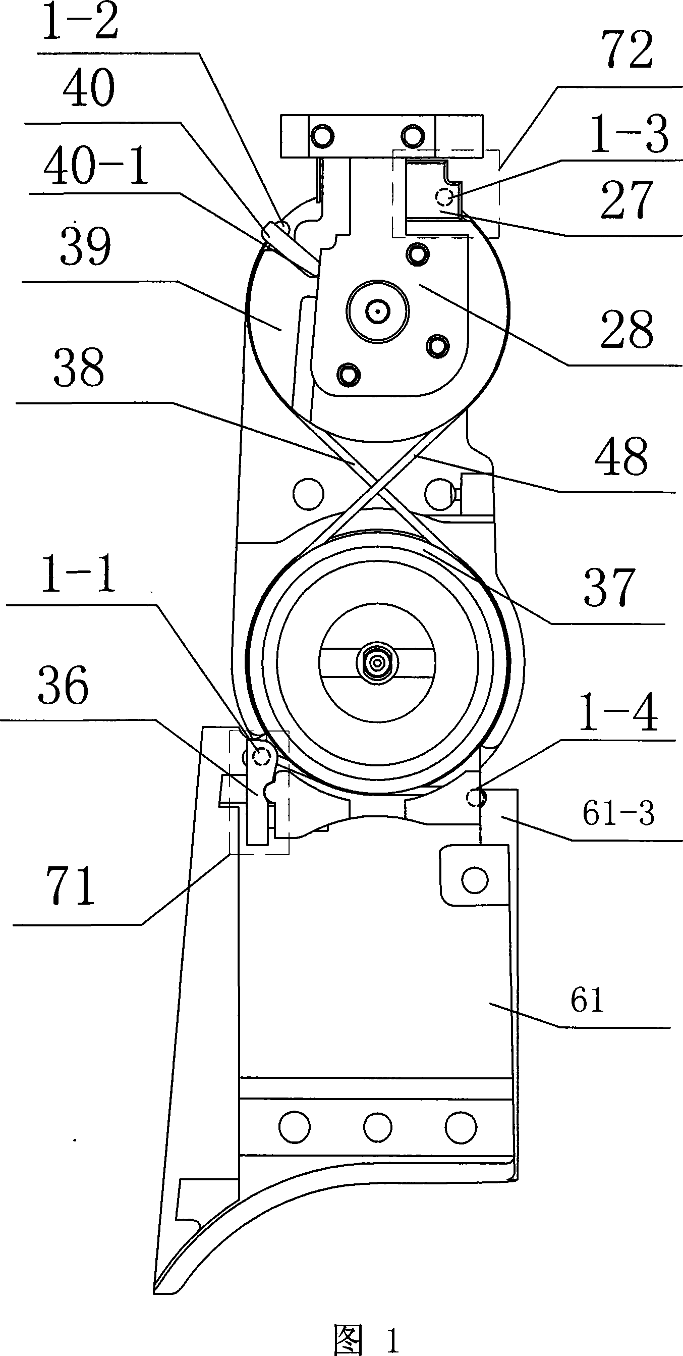
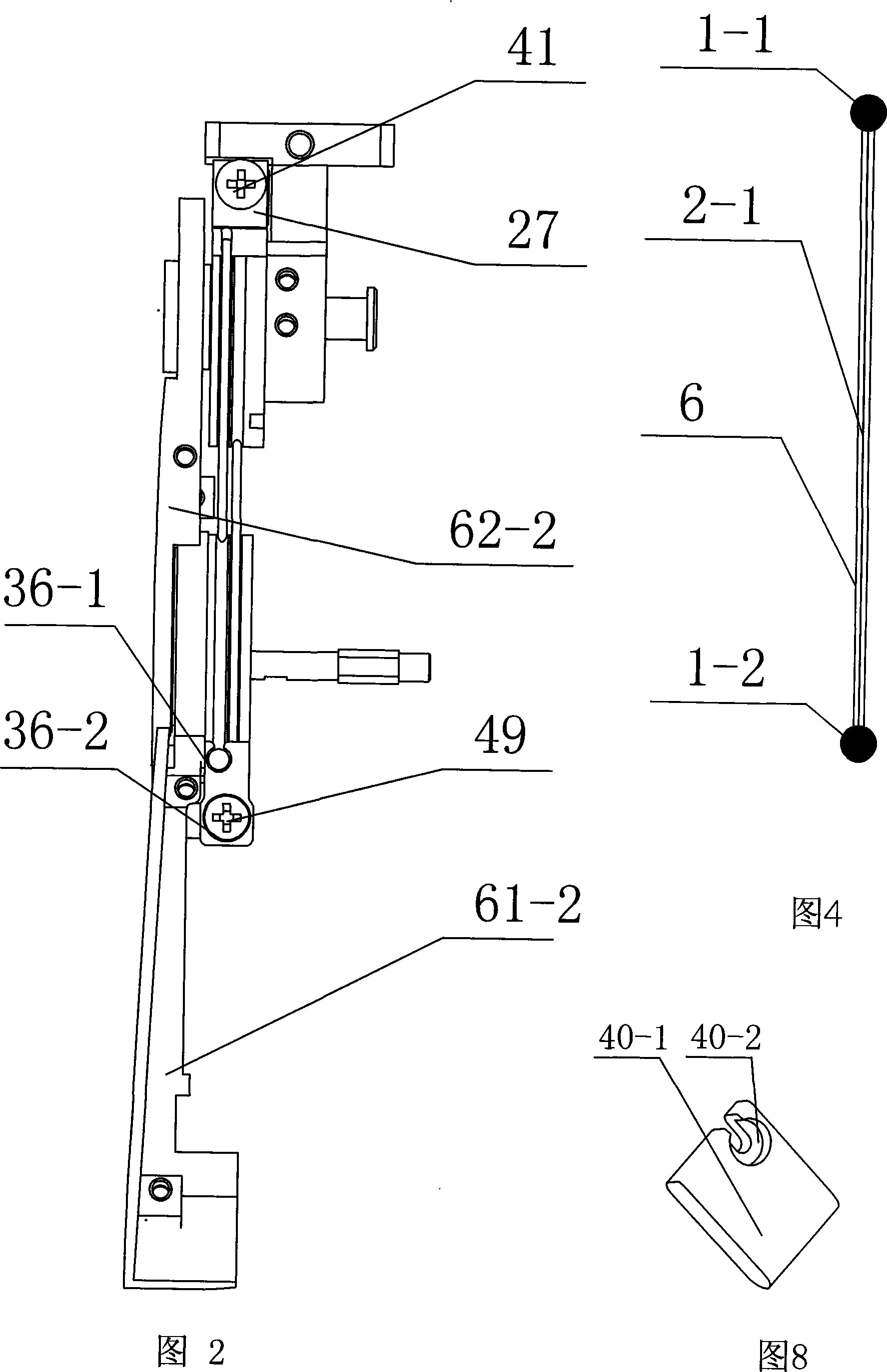
[0007] Embodiment 1: As shown in FIG. 1 , FIG. 5 , and FIG. 8 , the wire coupling transmission mechanism of the finger joints of the robot dexterous hand in this embodiment is composed of a first joint wire wheel 37 , a second joint wire wheel 39 , and a first wire member 38 , a second wire member 48, a first pre-tightening device 71, a second pre-tightening device 72, and a wire clip 40. The first wire member 38 and the second wire member 48 are respectively wound around the first joint wire wheel 37 and the second joint wire wheel 39 and cross into an "8" shape, the first wire member 38 is composed of the first steel ball 1-1, the second steel ball 1-2 and the first steel wire 2-1. A steel ball 1-1 and a second steel ball 1-2 are respectively fixed on both ends of the first steel wire 2-1, and the second steel wire 48 consists of the third steel ball 1-3 and the fourth steel ball 1 -4 and the second steel wire 2-2, the third steel ball 1-3 and the fourth steel ball 1-4 are r...

Example Embodiment

[0009] Embodiment 2: As shown in FIG. 1 , the first joint wire wheel 37 and the second joint wire wheel 39 in this embodiment have the same diameter. With such a structure, a coupling motion of a 1:1 angle is realized. Other components and connection relationships are the same as in the first embodiment.

Example Embodiment

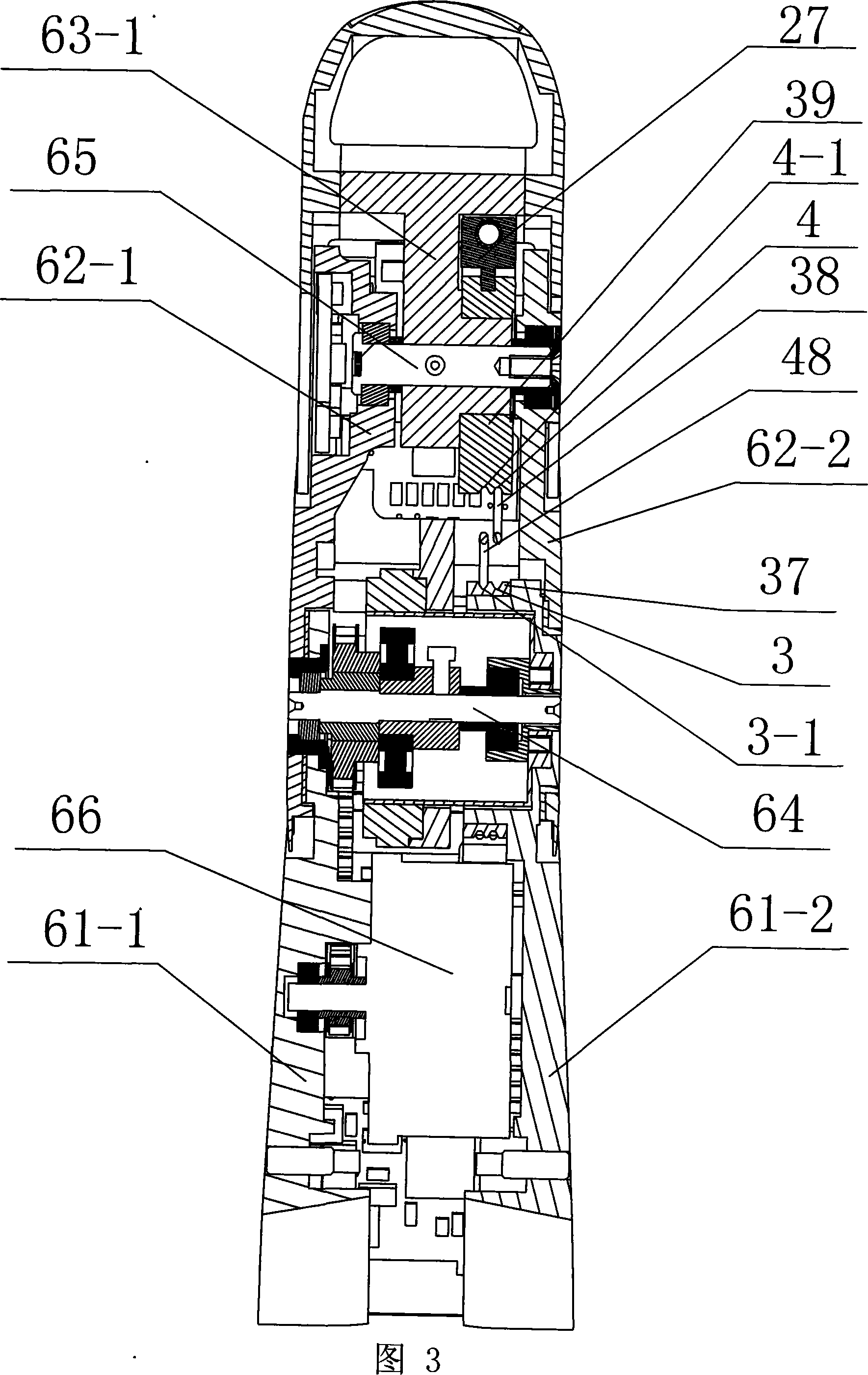
[0010] Embodiment 3: As shown in FIG. 3 , FIG. 6 , and FIG. 12 , the first joint wire wheel 37 described in this embodiment is provided with a first groove 3 and a second groove 3 - 1 . The two-joint wire wheel 39 is provided with a third groove 4 and a fourth groove 4-1. The two ends of the first wire member 38 are wound on the first groove 3 and the third groove 4 respectively. Both ends of the two steel wire members 48 are respectively wound on the second groove 3-1 and the fourth groove 4-1. With such a structure, the movement is stable. Other components and connection relationships are the same as in the first embodiment.


PUM


Abstract

The present invention relates to finger driving mechanism of robot, and is especially wire coupled finger driving mechanism of skillful robot hand. The wire coupled finger driving mechanism has one first wire piece and one second wire piece twisted separately on the first joint wire wheel and the second joint wire wheel and crossed to form one 8 figure shape, one wire clamping board inserted in the first groove, one first steel ball mounted inside the first pretension device, one second steel ball mounted inside the wire clamping board, one third steel ball mounted inside the second pretension device, and one fourth steel ball mounted inside the wire clamping board. The present invention realizes the coupling motion of two finger joints in the same direction and the same angle, and has the advantages of high simple structure, convenient pretension, high reliability, etc.

Description

technical field [0001] The invention relates to a transmission mechanism of a robot finger. Background technique [0002] As an important branch of robot technology, robot dexterous hand technology has achieved good results after decades of development, and some representative dexterous hands have been born one after another, such as Stanford / JPL hand, Utan / M.I.T hand, DLR hand, NASA hand, etc. Some advances are mainly reflected in mechanical structure, drive, sensing, integration and control. Most of the dexterous hands that have been successfully developed at present adopt the arrangement of degrees of freedom similar to human hands: four joints and three degrees of freedom. There are two joints (collectively called base joints) and two degrees of freedom at the root of the finger to realize the bending and sideways movement of the finger; there are two joints and one degree of freedom at the finger part, and the two joints of the finger part move through the coupling mo...

Claims


Application Information

Patent Timeline
IPC IPC(8): B25J17/00B25J15/00
Inventor 刘伊威刘宏兰天金明河樊绍巍
Owner HARBIN INST OF TECH
Why Eureka
Try Eureka