Entirety type electric and manual hydraulic lifter for overturning driving cab

A cab, integral technology, applied in the field of electric and manual hydraulic lifts for integral cab overturning, can solve the problems of poor assembly process, unsafe, oil leakage, etc., to achieve clean structure, reliable leakage prevention and processing. good craftsmanship

Inactive Publication Date: 2008-01-09
王树革
View PDF1 Cites 16 Cited by
  • Summary
  • Abstract
  • Description
  • Claims
  • Application Information

AI Technical Summary

Problems solved by technology

The first and second types of overturning cabs are labor-intensive and unsafe for the driver; the third type has a split cab overturner. The oil pump and hydraulic cylinder of the overturner are separated into two parts, and the middle is connected by an oil pipe. , the oil pipe is easily worn during use, causing oil leakage in the system, which makes the turner work invalid, and secondly, the poor sealing of the pipe joint causes oil leakage, and the assembly process is poor
On December 21, 2005, the Chinese patent disclosed that the patent number is: 200510016856.9, and the name is: electric / manual lifting device for cab turning. This patent is an electric and manual integration, which overcomes the above-mentioned shortcomings. Although it is more convenient and applicable, However, 1. The whole device cannot be lifted horizontally (because of the self-weight check valve)
2. The lifting force is limited by the diameter and number (two) of the sliding plungers of the plunger pump (because the electric pump adopts a split structure), so it is difficult to increase the lifting force
3. The horizontal volume of the main body is too long, and the number of valve holes is too large, which makes the manufacturing process cumbersome and the production cost is relatively high.
4. Due to the external installation of the manual pump device system and the body, it is easy to cause thread loosening during actual use, making the operation of the manual pump device invalid
5. Since the manual pump device uses the up and down swing method to inject high-pressure oil into the system, but in the actual loading and use, the up and down swing method has no layout space, so it brings difficulties to the layout and operation of the whole vehicle
7. The manufacturing cost of arranging the follow-up device inside the piston rod is higher than that inside the lifting body
8. Only short-distance manual operation can be realized, but long-distance manual operation and long-distance button electric control and remote control cannot be realized.

Method used


Image

  • Entirety type electric and manual hydraulic lifter for overturning driving cab
  • Entirety type electric and manual hydraulic lifter for overturning driving cab
  • Entirety type electric and manual hydraulic lifter for overturning driving cab

Examples


Embodiment 1

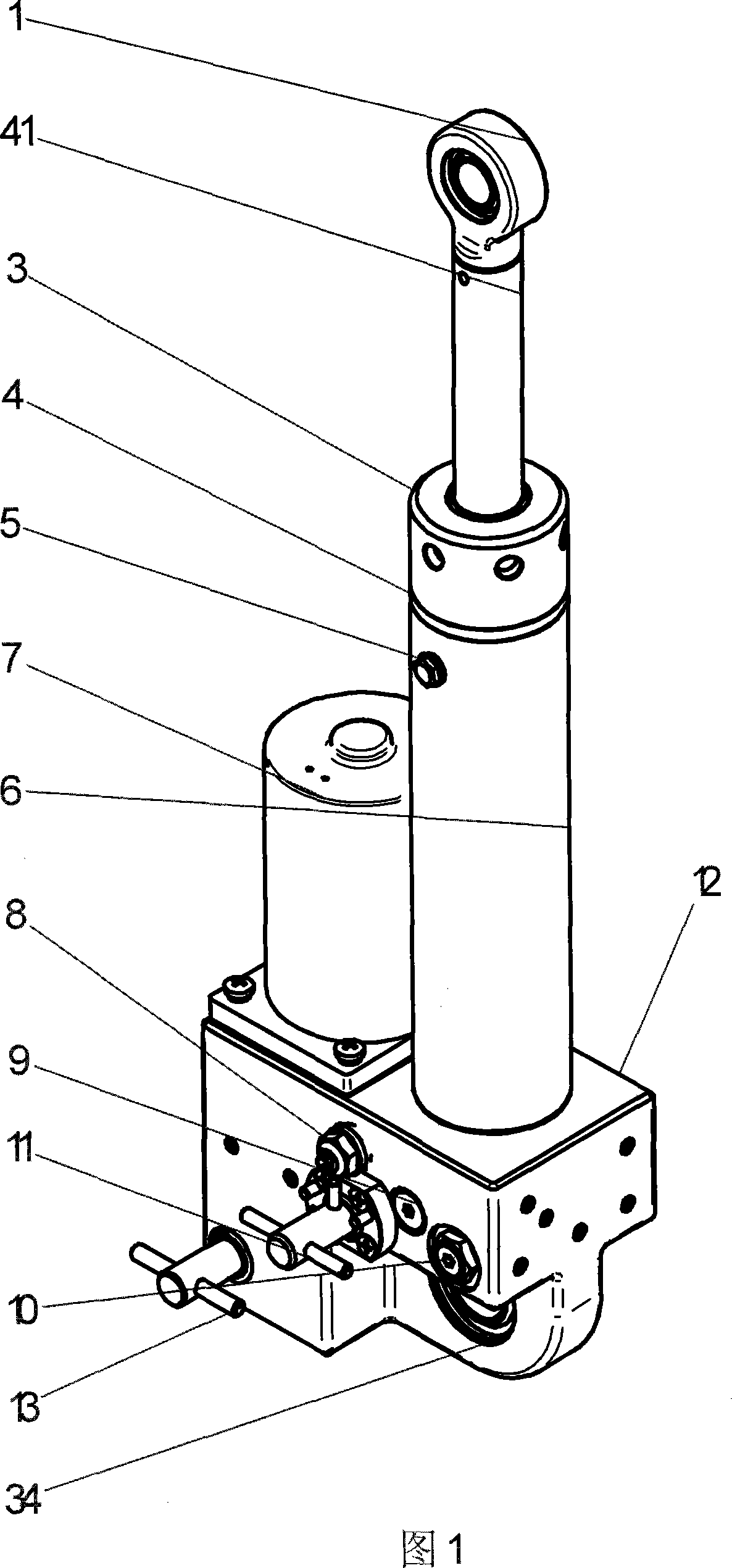
[0085] The follow-up oil cylinder 35 is arranged on the left end face of the main body, and the lift cylinder 40 does not contain a follow-up device. The mechanism 15 in the way of rotating the swing cam of the manual pump is arranged on the rear end surface on the left side of the lifting body;

[0086] The present invention is composed of a lifting body 12 , an integral hydraulic pump 24 , a manual pump 13 , a servo cylinder 35 and a lifting cylinder 40 .

[0087] On the left side of the lift body, a motor 7, a dust-proof and shock-absorbing pad 23, an electric pump anti-leakage device 21, and an integral hydraulic pump 24 are installed in sequence from top to bottom, and a manual pump 13 and a follower Lifting oil cylinder 40 is installed on oil cylinder 35, right upper end face;

[0088] On the front of the lifting body, a manual pump 13 and an operating mechanism, a relief valve 8, a reversing valve 11 and an operating mechanism, a one-way throttle valve 9 and a hydrauli...

Embodiment 2

[0111] In order to realize the automatic opening of the cab clamp lock, the present invention adopts an automatic unlocking device, that is, the follow-up oil cylinder installed on the left end surface of the body in embodiment 1 is replaced with an unlocking oil cylinder, and the lifting oil cylinder in embodiment 1 is replaced with a follow-up oil cylinder replace;

[0112] Replace the two-position four-way rotary reversing valve with a two-position four-way differential reversing valve,

[0113] Arrange the unlocking cylinder on the left end face of the main body, and the lifting cylinder 40 contains an oil-guiding groove type follow-up device (type B lifting cylinder described in the technical solution), and a differential oil passage is formed by a reversing valve 11. The upper and lower chambers of the follow-up lifting cylinder 20 provide high-pressure oil to complete the lifting, and the mechanism 15 in the form of a manual pump rotating swing cam is arranged on the re...

Embodiment 3

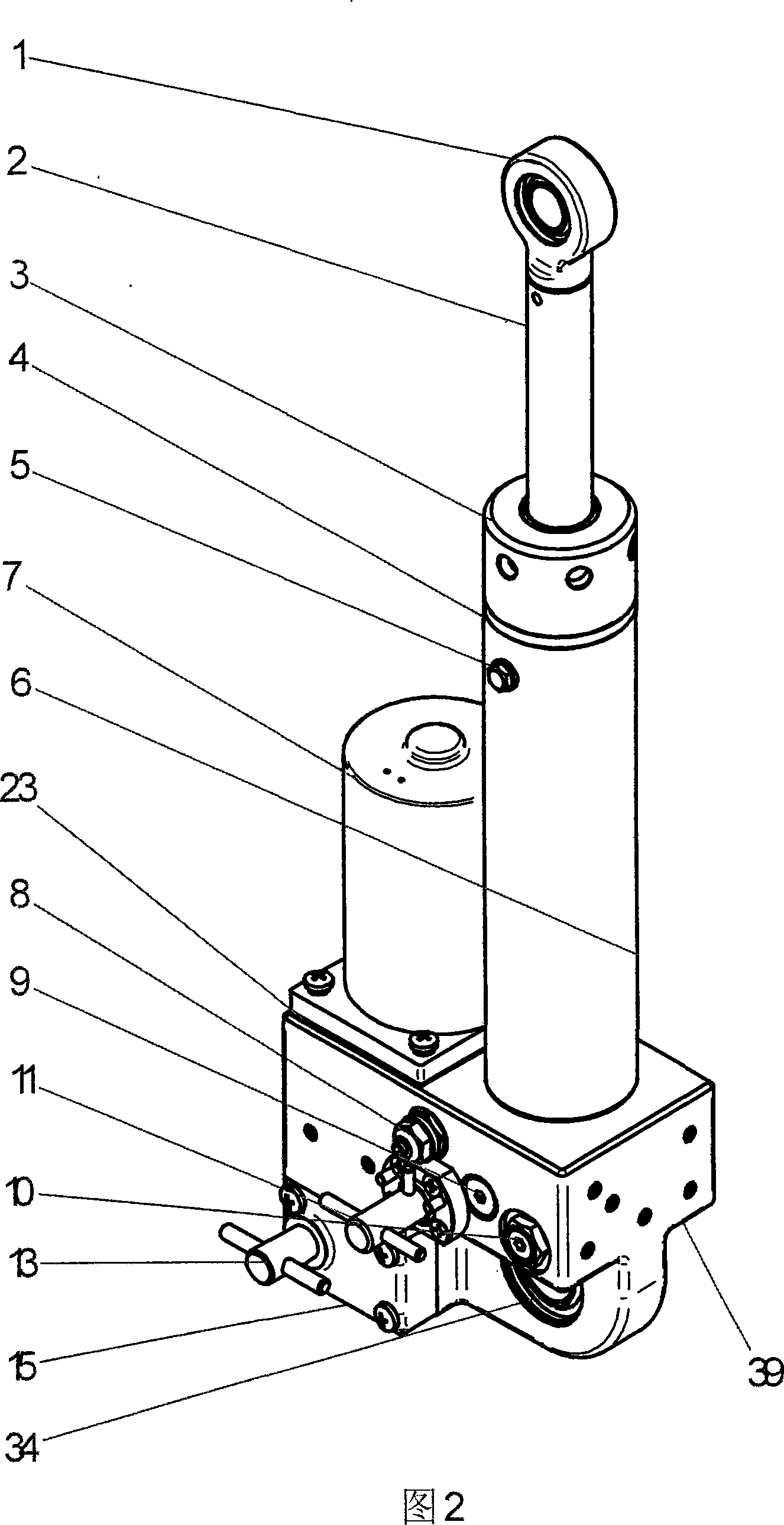
[0120] Considering the need for a large follow-up stroke of the cab, the vertical follow-up oil cylinder 36 is arranged on the lower left end surface of the body 39, and the lift cylinder 40 does not contain a follow-up device (type A lift cylinder described in the technical solution). The mechanism 15 of the manual pump rotating swing cam is arranged on the front face of the left side of the body;

[0121] The layout of all other parts is identical with embodiment 1;

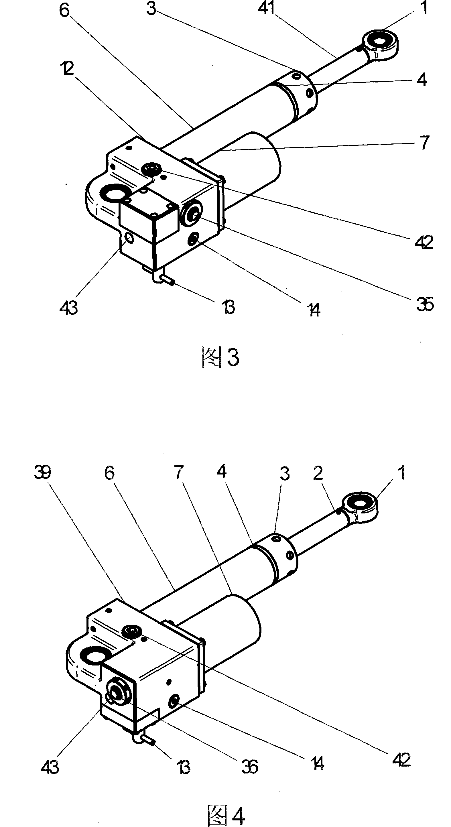
[0122] What present embodiment adopts is body 39, and body has 37 holes altogether and sees figure mark (seeing as shown in Figure 19):

[0123] The difference between body 39 and body 12 is:

[0124] The 011 channel of the body 12 is horizontal, and the 011 channel of the body 39 is vertical;

[0125] Hole 012 and hole 013 of body 12 are on the left rear side of the body, and holes 012 and 013 of body 39 are on the left front side of the body; The outer groove of the cam structure of the manual pump is arra...


PUM


Abstract

The electrically driven and hand driven hydraulic lifting machine for turning integral cab belongs to the field of automotive technology. The electrically driven and hand driven hydraulic lifting machine includes electric pump, hand pump and its operating mechanism, change valve and its operating mechanism, non-return valve for hand pump, one-way throttle valve, hydraulically controlled non-return valve, servo mechanism, unlocking oil cylinder, sealing member and control oil path mounted integrally inside one housing; lifting oil cylinder, piston and relevant parts integrated and mounted on the housing; and motor for the electric pump on the housing. The electrically driven and hand driven hydraulic lifting machine has reliable operation, wide application range, great lifting force and other advantages.

Description

technical field [0001] The invention belongs to the technical field of automobiles, and specifically relates to electric and manual hydraulic lifts for turning over integral cabs with five structural forms, and the international patent classification number is B62D33 / 067. Background technique [0002] The existing cab overturning device mainly has the following three forms at present, one is the torsion spring type, a torsion spring is installed on the front axle of the cab, and a pre-torsion is given to reduce the gravity of the cab; the second is One is to adopt a screw structure; the third is to use a hydraulic mechanism manually or electrically; the above three methods all have different defects. The first and second types of overturning cabs are labor-intensive and unsafe for the driver; the third type has a split cab overturner. The oil pump and hydraulic cylinder of the overturner are separated into two parts, and the middle is connected by an oil pipe. 1. The oil pi...

Claims


Application Information

Patent Timeline
Patent Type & Authority Applications(China)
IPC IPC(8): B62D33/067F15B13/06
Inventor 王树革
Owner 王树革
Why Eureka
Try Eureka