Chemical hydride hydrogen storing material system, hydrogen preparing method and hydrogen preparing device

A technology for hydrogen storage material and hydrogen production device, which is applied in the production of borane/diborane hydride and hydrogen, etc., can solve the problem of reducing the load firmness, and the hydrogen storage system cannot respond quickly to changes in hydrogen demand and reduce the system hydrogen storage capacity and other issues, to achieve the effect of reducing material costs, prolonging hydrogen production efficiency, and improving hydrogen storage capacity

Inactive Publication Date: 2008-01-09
INST OF METAL RESEARCH - CHINESE ACAD OF SCI
View PDF0 Cites 14 Cited by
  • Summary
  • Abstract
  • Description
  • Claims
  • Application Information

AI Technical Summary

Problems solved by technology

[0008] (2) Adding lye will destroy the catalyst/carrier structure, reduce the firmness of the load, and cause catalyst loss;
[0009] (3) During the continuous hydrolysis reaction, it is difficult to remove the hydrolyzate effectively in time, which will cover the surface of the catalyst, resulting in reduced catalytic activity, i

Method used


Image

  • Chemical hydride hydrogen storing material system, hydrogen preparing method and hydrogen preparing device
  • Chemical hydride hydrogen storing material system, hydrogen preparing method and hydrogen preparing device
  • Chemical hydride hydrogen storing material system, hydrogen preparing method and hydrogen preparing device

Examples


Embodiment 1

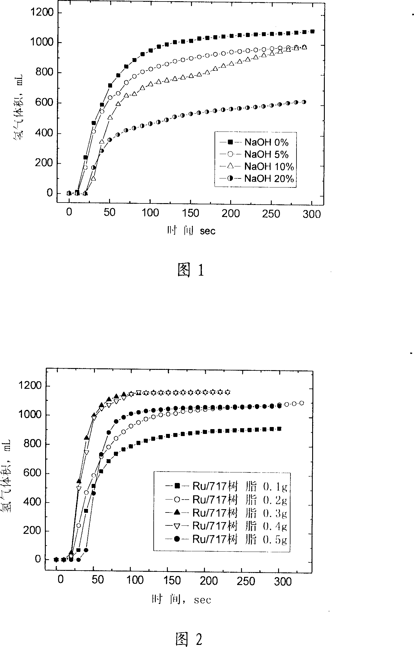
[0050] Adopt no NaOH in the raw material, all the other raw materials and test method, test condition are the same as comparative example 1. The dosage of the catalyst is 0.1-0.5 grams, accounting for 2-9% of the total weight of the hydrogen storage material system.

[0051] Figure 2 shows the effect of the amount of catalyst on the amount of hydrogen produced by the system and the rate of hydrogen production. With the increase of the amount of catalyst, the amount of hydrogen production and the rate of hydrogen production both increased.

Embodiment 2

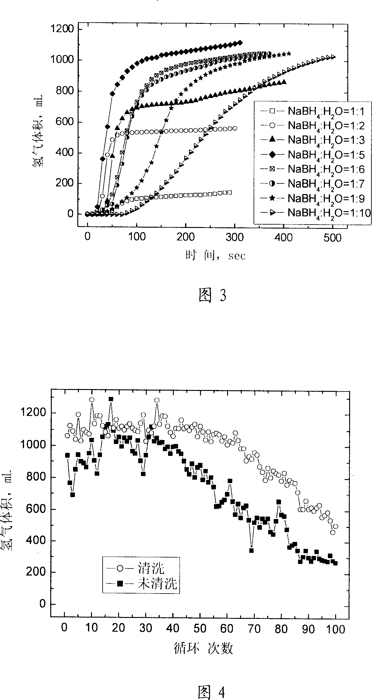
[0053] Adopt raw material and test method, test condition with embodiment 1. NaBH 4 The concentration of the aqueous solution is: NaBH 4 :H 2 O=1:1-1:10. The amount of catalyst used is 0.3 g, accounting for 5% of the total weight of the hydrogen storage material system.

[0054] Figure 3 gives the NaBH 4 The influence of the concentration on the amount of hydrogen produced and the rate of hydrogen production in the system. with NaBH 4 As the concentration increases, the amount of hydrogen produced by the system and the rate of hydrogen production increase first, and reach the optimum when it reaches 1:5, and continue to increase the NaBH 4 Concentrations lead to a decrease in the rate of hydrogen production.

Embodiment 3

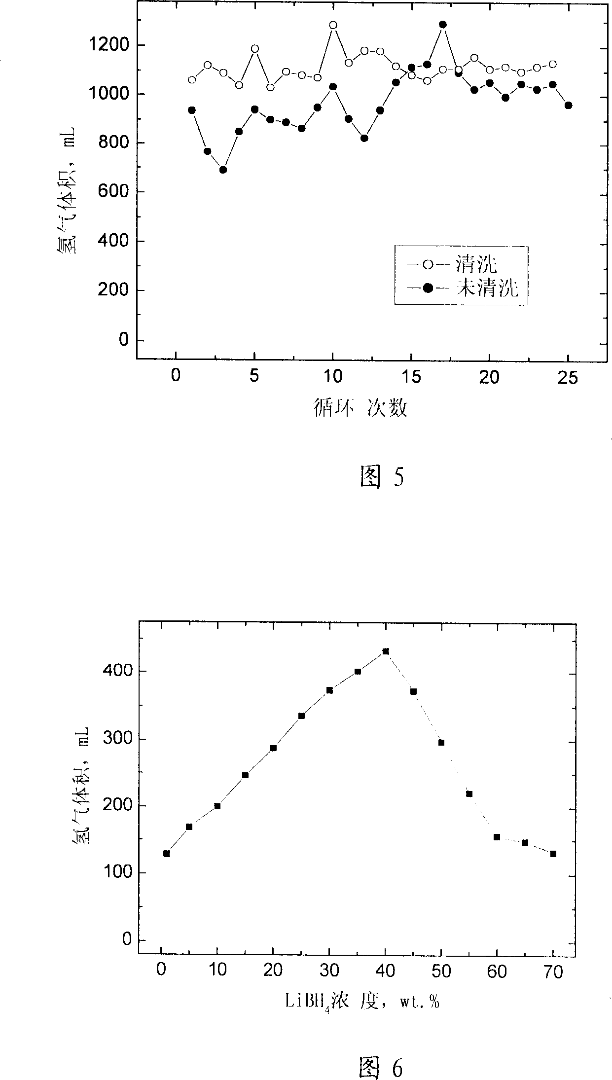
[0058] Adopt raw material and test method, test condition with embodiment 1. Figure 5 shows the influence of the number of hydrolysis cycles and catalyst cleaning treatment on the hydrogen production of the system without adding NaOH. For the material system without adding NaOH, the amount of hydrogen production is generally stable with the increase of the number of cycles, and the catalyst cleaning treatment can further improve the stability of the hydrogen release amount.


PUM


Abstract

This invention relates to the chemical hydrogen storage material system comprising alkali metals and alkaline-earth metals borohydrides, and the hydrolyzation of the same for producing hydrogen, and the equipment therefore. The chemical hydride hydrogen storage material system consists of: chemical hydrides, water, catalyst and the carrier. This inventive hydrogen generator consists of: raw material storage unit, water tank, mixer, pump, reactor, accumulator and collector. The hydride powder and water are mixed in the mixer, and then in the reactor equipped with catalyst, the hydrolyzation takes place and producing hydrogen. In this hydrogen storage material contains no stabilizer, so reducing the cost and increasing hydrogen production property. This invention has also advantages of: fast responsive time, fast hydrogen supply rate, automatically regulating hydrogen production process based on the requirement of terminal unit, so it is the useful technique and equipment for vehicle carried hydrogen storage and mobile electric power supply.

Description

Technical field [0001] The invention relates to a chemical hydride hydrogen storage material system and hydrogen production technology, in particular to an alkali metal or alkaline earth metal borohydride hydrogen storage material system, a hydrolysis reaction hydrogen production method and a hydrogen production device. Background technique [0002] Developing a high-performance hydrogen storage system to provide hydrogen sources for hydrogen fuel cell vehicles and various military and civilian mobile power sources is a key link in the application of hydrogen energy. Among various hydrogen storage methods, material-based hydrogen storage is significantly superior to high-pressure gas cylinders and cryogenic liquid hydrogen in terms of safety and hydrogen storage density, and is recognized as the most promising. However, after years of research, there is currently no reversible hydrogen storage material that can meet the comprehensive requirements of the vehicle-mounted hydro...

Claims


Application Information

Patent Timeline
IPC IPC(8): C01B6/21C01B3/02
Inventor 王平刘红成会明
Owner INST OF METAL RESEARCH - CHINESE ACAD OF SCI
Why Eureka
Try Eureka