Original soft clay hollow cylinder sample inner core cutting device

A technology for hollow cylindrical samples and soft clay, which is applied in the field of core cutters for hollow cylindrical samples of undisturbed soft clay, which can solve problems such as hindering drilling, increasing sample disturbance, and lack of support points, so as to reduce propulsion resistance , to avoid the effect of secondary adhesion

Inactive Publication Date: 2008-01-09
ZHEJIANG UNIV
View PDF0 Cites 7 Cited by
  • Summary
  • Abstract
  • Description
  • Claims
  • Application Information

AI Technical Summary

Problems solved by technology

[0003] However, neither of the above two methods can be directly applied to the preparation of large-scale soft clay samples in the southeastern coastal areas of my country to overcome the size effect and end effect (usually the sample height is above 20cm)
Practical operation found that for large-size soft clay samples, the mechanical step-by-step drill-pipe coring method has the following disadvantages: 1) The step-by-step drill-pipe coring method makes the sample lose its viability after the first small hole coring. The alignment of the hole center means that the drill pipe lacks a supporting point in the subsequent drilling process. For soft clay, it is easy to cause the vertical advancement of the coring surface to be unable to be maintained, resulting in partial hole; 2) Step by step The multiple hole forming method increases the probability of disturbing the sample; 3) The more critical issue is to use a single drill to take the soil. Due to the high viscosity of the soft clay, the cut hole core soil chips will not fall under the action of gravity. It falls off, but adheres to the inner wall for the second time, and adheres to the hole wall soil t

Method used


Image

  • Original soft clay hollow cylinder sample inner core cutting device
  • Original soft clay hollow cylinder sample inner core cutting device
  • Original soft clay hollow cylinder sample inner core cutting device

Examples


Example Embodiment

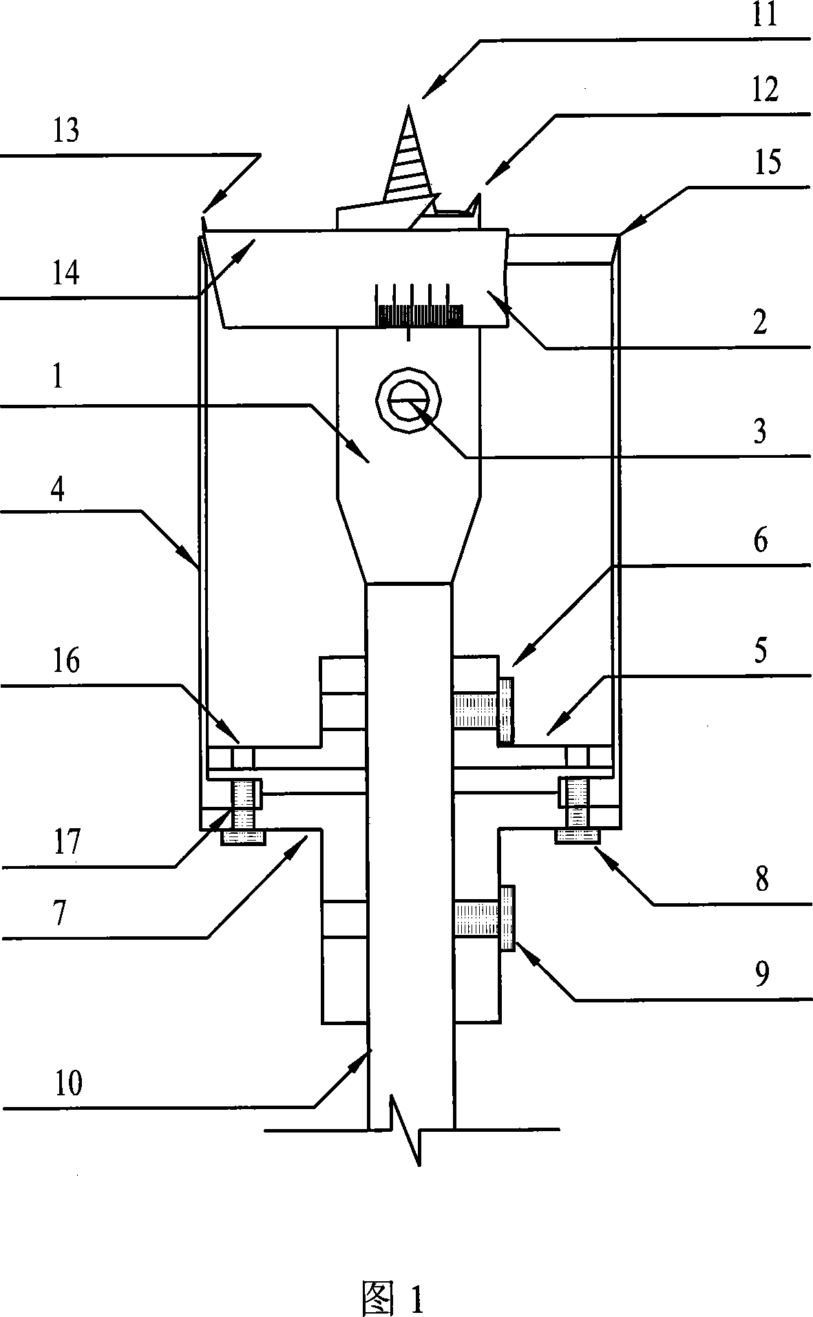
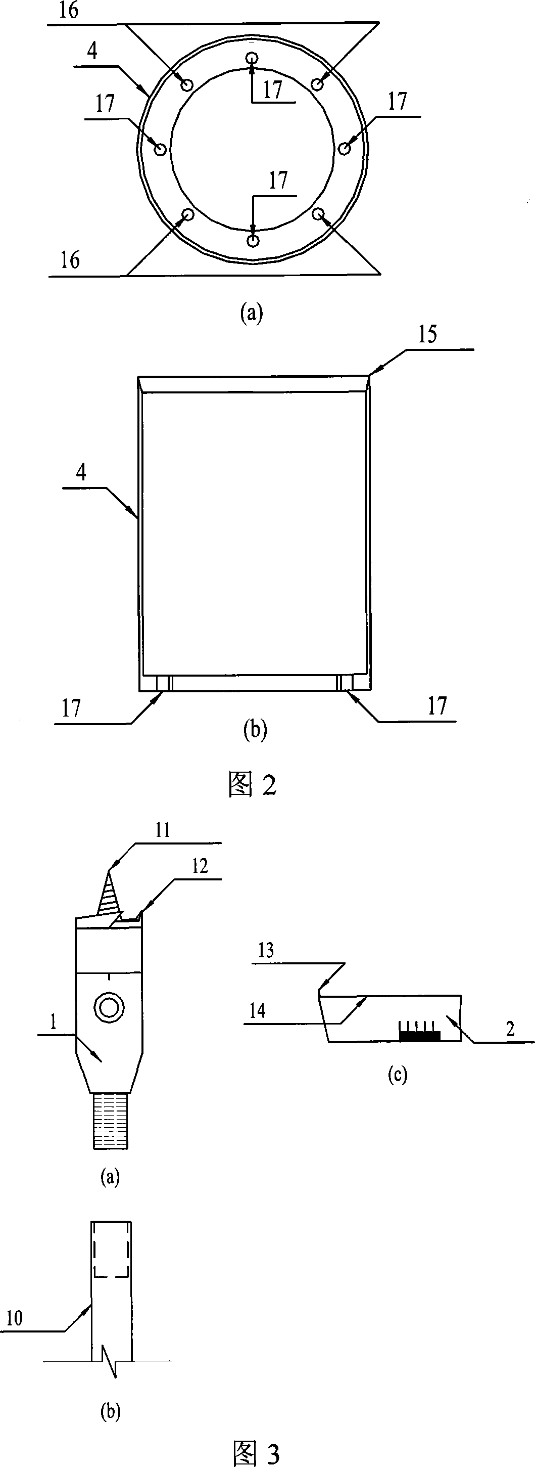
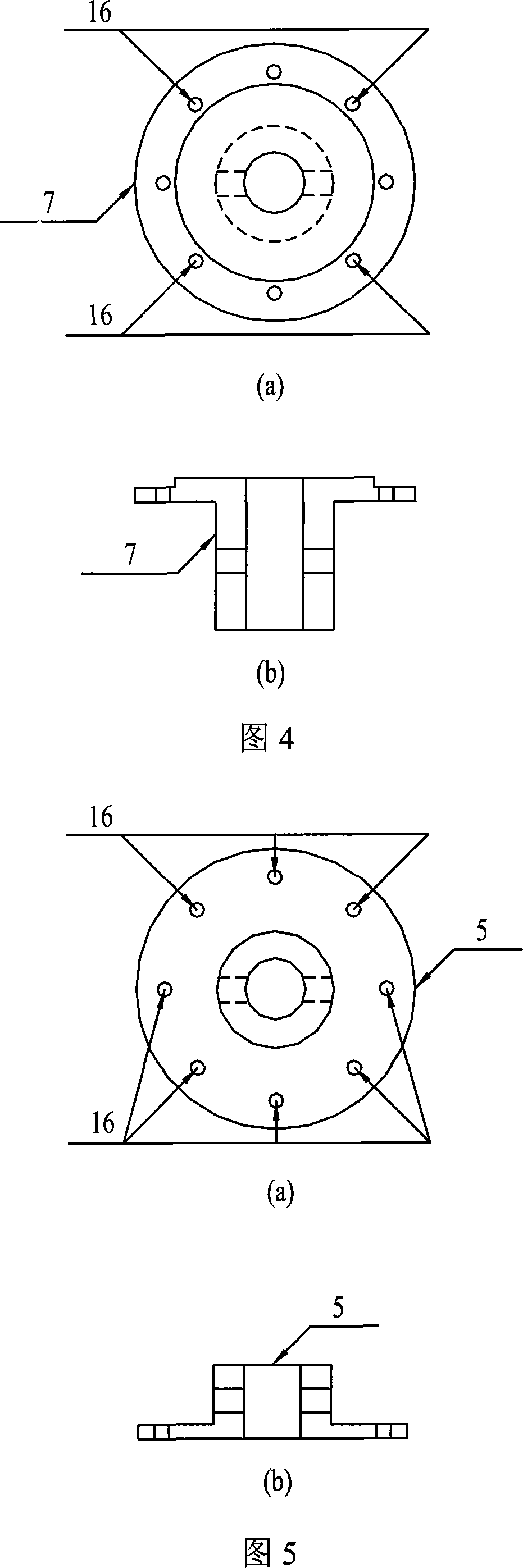
[0022] As shown in Figures 1, 2, 3, 4, 5, 6, the original soft clay hollow cylindrical sample core cutter has a protective tube 4, the upper end of the protective tube 4 is provided with a cutting edge 15, and the lower end of the protective tube 4 passes through the protective tube Bottom support-protective tube positioning screw 8 and protective tube-protective tube bottom support connecting screw holes 17 are connected to the detachable protective tube bottom bracket 7, and the detachable protective tube bottom bracket 7 is provided with a detachable earth holding bracket 5 for detachable soil holding The support 5 is provided with a pressure relief hole 16, and the main drill bit 1 is provided in the middle of the protective cylinder 4. The main drill bit 1 is composed of a spiral drill bit 11 and an inner edge blade 12, and is connected with a drill pipe 10, which passes through the detachable soil holder 5. The detachable bottom bracket 7 of the protective tube is fixed by t...


PUM


Abstract

The invention discloses a cut and get core machine of status quo soft clay hollowness column sample. It has pile casing, setting up the cutting edge on the superior extremity of pile casing, the inferior extremity of the pile casing connects with pallet of dismantle type pile casing by pile casing pallet hyphen pile casing fixed screw, fixing the dismantle type filling soil torr on the surface of the dismantle type pile casing pallet, fixing the pressure release hole on the dismantle type filling soil torr, fixing the direct bit in the middle of pile casing, the direct bit is made up of auger bit and inner margin blade, and connects with the drill pipe, the drill pipe traverses dismantle type filling soil torr, pallet of dismantle type pile casing, and is fixed by filling soil torr hyphen drill pipe fixed screw,pile casing hyphen drill pipe fixed screw, the dismantle type blade slice is made up of the inner margin blade,level blade, and connects stiffly with the direct bit by blade fixed screw. The pile casing is cylindrical form. The cut and get machine can prepare successfully status quo soft clay hollowness column sample, the disturbing of bringing in the process of cutting,the influence of hustle soil is small, providing the equipment bond guarantee for the experimental investigation of status quo soft clay under the complex stress condition.

Description

technical field [0001] The invention relates to an inner core cutter of a hollow cylindrical sample of soft clay. Background technique [0002] Molding the soil into a hollow cylindrical sample provides the possibility to simulate the stress state of the soil under complex stress path conditions in the laboratory and carry out related property research. However, there are few experimental studies on undisturbed clay hollow cylinder samples at home and abroad. One of the important reasons is that there is no "universal" technology suitable for various soil properties for cutting the inner core of clay samples. In principle, there are two main coring methods for undisturbed clay samples: mechanical and electroosmotic. The mechanical coring method is represented by the research results of the Imperial College of Technology in the United Kingdom. The application object is London super-consolidated clay with high strength. The method uses 7 drills with different diameters to cor...

Claims


Application Information

Patent Timeline
IPC IPC(8): G01N1/08G01N1/28
Inventor 沈扬周建温晓贵张金良张泉芳杰瑞·沙顿
Owner ZHEJIANG UNIV
Why Eureka
Try Eureka