
Wafer linear cutting slurry filtering device and cleaning control system thereof

A filter device and wire cutting technology, which is applied in the direction of filter circuit, filter separation, fixed filter element filter, etc., can solve the problems of mud dirt, abnormal disconnection, and reduced production efficiency, so as to avoid secondary adhesion and improve The effect of improving life and efficiency

Pending Publication Date: 2020-08-11
FIRST SEMICON MATERIALS
View PDF0 Cites 0 Cited by
  • Summary
  • Abstract
  • Description
  • Claims
  • Application Information

AI Technical Summary

Problems solved by technology

[0003] In the prior art, the mud produced after wire cutting wafers, mixed with broken wafers or graphite strip debris, is easy to leak into the mud tank through the mud filter, and is pumped into the wire cutting equipment during the cycle cutting process, thus entering the steel wire In order to prevent broken chips or graphite strip debris from leaking through the filter holes of the filter, and then pumped into the wire cutting equipment through the mud pipe again, it is generally installed at the mouth of the mud pipe Stockings, filter chips or graphite bar chips
[0004] However, because the stockings need to be replaced frequently, and the mud is dirty and smelly, and the stockings after mud filtration have the risk of slag and injury to the hands, etc., this leads to workers' laziness in changing stockings. Workers often ignore stockings. It will be accompanied by repeated reversal of the mud flow direction, broken stockings, equipment jumpers and broken wires, and the improvement effect is poor; in addition, the mud is dirty, and the enthusiasm of workers to change and wash the filter is poor, which will easily lead to filter blockage and affect the efficiency of mud flow. Thereby reducing the efficiency of production and at the same time affecting the life of the filter screen

Method used


Image

  • Wafer linear cutting slurry filtering device and cleaning control system thereof
  • Wafer linear cutting slurry filtering device and cleaning control system thereof
  • Wafer linear cutting slurry filtering device and cleaning control system thereof

Examples


Embodiment Construction

[0048] The specific implementation manners of the present invention will be further described in detail below in conjunction with the accompanying drawings and embodiments. The following examples are used to illustrate the present invention, but are not intended to limit the scope of the present invention.

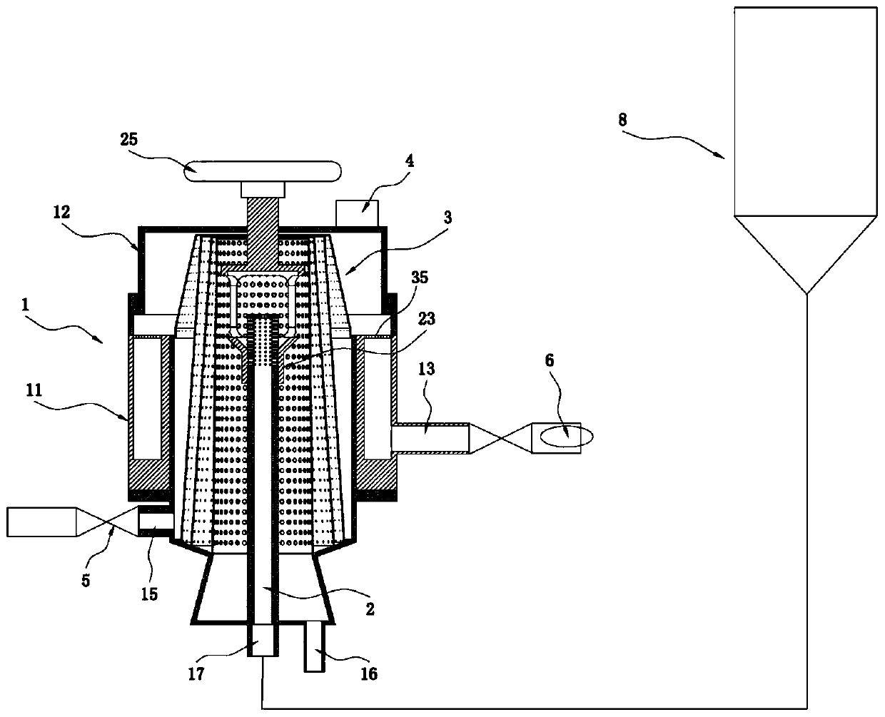
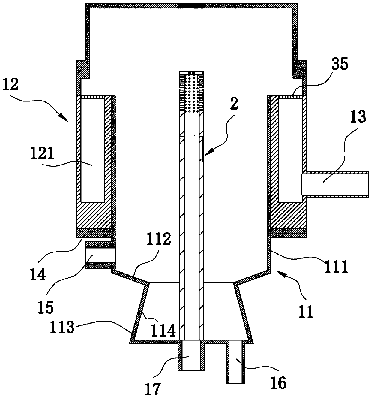
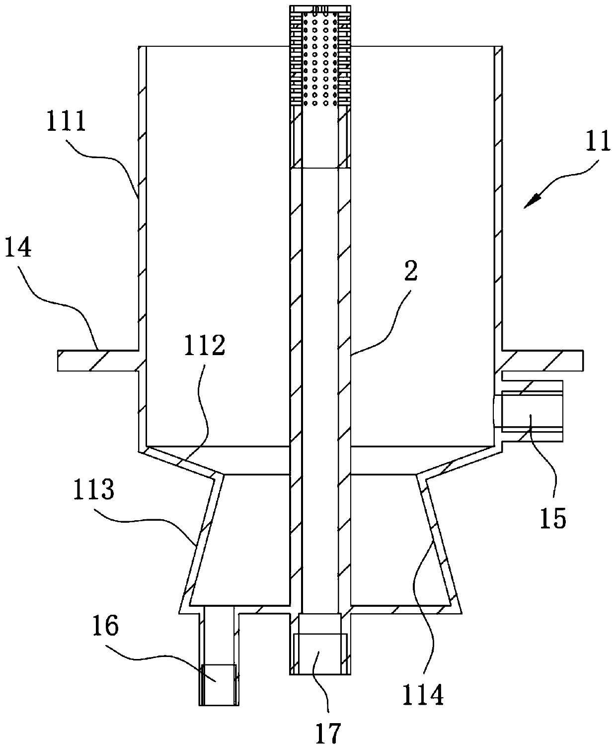
[0049] refer to Figure 1-Figure 7 , the present embodiment provides a wafer wire cutting mud filter device, comprising:

[0050] Sedimentation cylinder 1, used for settling mud debris, deposition cylinder 1 is provided with mud outlet 13;

[0051] The filter assembly 3 arranged in the deposition cylinder 1, the deposition cylinder 1 is separated by the filter assembly 3 to form an inner cavity and an outer cavity, and the mud outlet 13, the outer cavity and the inner cavity are connected in sequence, and the filter assembly 3 includes at least one layer of filter screen 31. The mesh surface of the net 31 is arranged obliquely with the vertical direction;

[0052] The j...


PUM


Abstract

The invention relates to the technical field of wafer linear cutting, and in particular to a wafer linear cutting slurry filtering device, and a cleaning control system thereof. The wafer linear cutting slurry filtering device comprises a deposition cylinder used for settling slurry disintegrating slag, wherein the deposition cylinder is provided with a slurry outlet; a filtering assembly which isarranged in the deposition cylinder, wherein the deposition cylinder is separated into an inner cavity and an outer cavity through the filtering assembly, the slurry outlet, the outer cavity and theinner cavity are sequentially communicated, the filtering assembly comprises at least one layer of filtering screen, and the screen surface of the filtering screen is obliquely arranged in the vertical direction; and a jet flow pipe which is provided with jet flow holes, wherein the jet flow holes are contained in the inner cavity and used for injecting slurry into the inner cavity. According to the invention, the stress, abrasion and debris filtering amount of the filter screen can be reduced, the service life of the filter screen is prolonged, effective filtration of slurry is realized, theslurry filtering efficiency is improved, and the filter screen has a self-cleaning effect in the filtering process; in addition, automatic inclination of the filtering device is achieved, manpower isreduced, and the production efficiency is improved.

Description

technical field [0001] The invention relates to the technical field of wafer wire cutting, in particular to a wafer wire cutting mud filtering device and a cleaning control system thereof. Background technique [0002] The existing wafer wire cutting equipment will go through at least two filtering processes during the wire cutting process, one is the wire cutting wheel axle box mud filter; the other is the mud filter, and most of the large particles of impurities have been filtered through the above two filtering devices , and the filtered mud is re-pumped onto the wire-cut steel wire and wafer surface through the mud filter pump of the wire-cutting machine, and the mud mixture after wire-cutting undergoes the above-mentioned two filtering processes again, and the wire-cutting of the wafer is completed again and again. [0003] In the prior art, the mud produced after wire cutting wafers, mixed with broken wafers or graphite strip debris, is easy to leak into the mud tank t...

Claims


Application Information

Patent Timeline
Patent Type & Authority Applications(China)
IPC IPC(8): B01D29/35B01D29/60B01D29/72B01D36/04C02F11/00
CPCC02F11/00B01D36/04B01D29/35B01D29/603B01D29/72
Inventor 罗爱斌周铁军陈章水宾启雄叶水景严卫东
Owner FIRST SEMICON MATERIALS
Learn More