Automatic gain control circuit

An automatic gain control, circuit technology, applied in gain control, amplification control, electrical components, etc., can solve problems such as poor rise time and release time stability

Inactive Publication Date: 2008-01-09
YAMAHA CORP
View PDF1 Cites 19 Cited by
  • Summary
  • Abstract
  • Description
  • Claims
  • Application Information

AI Technical Summary

Problems solved by technology

Therefore, if this circuit is used in an AGC circuit, there will be a problem that the stability of the rise time and release time will deteriorate

Method used


Image

  • Automatic gain control circuit
  • Automatic gain control circuit
  • Automatic gain control circuit

Examples


no. 1 example

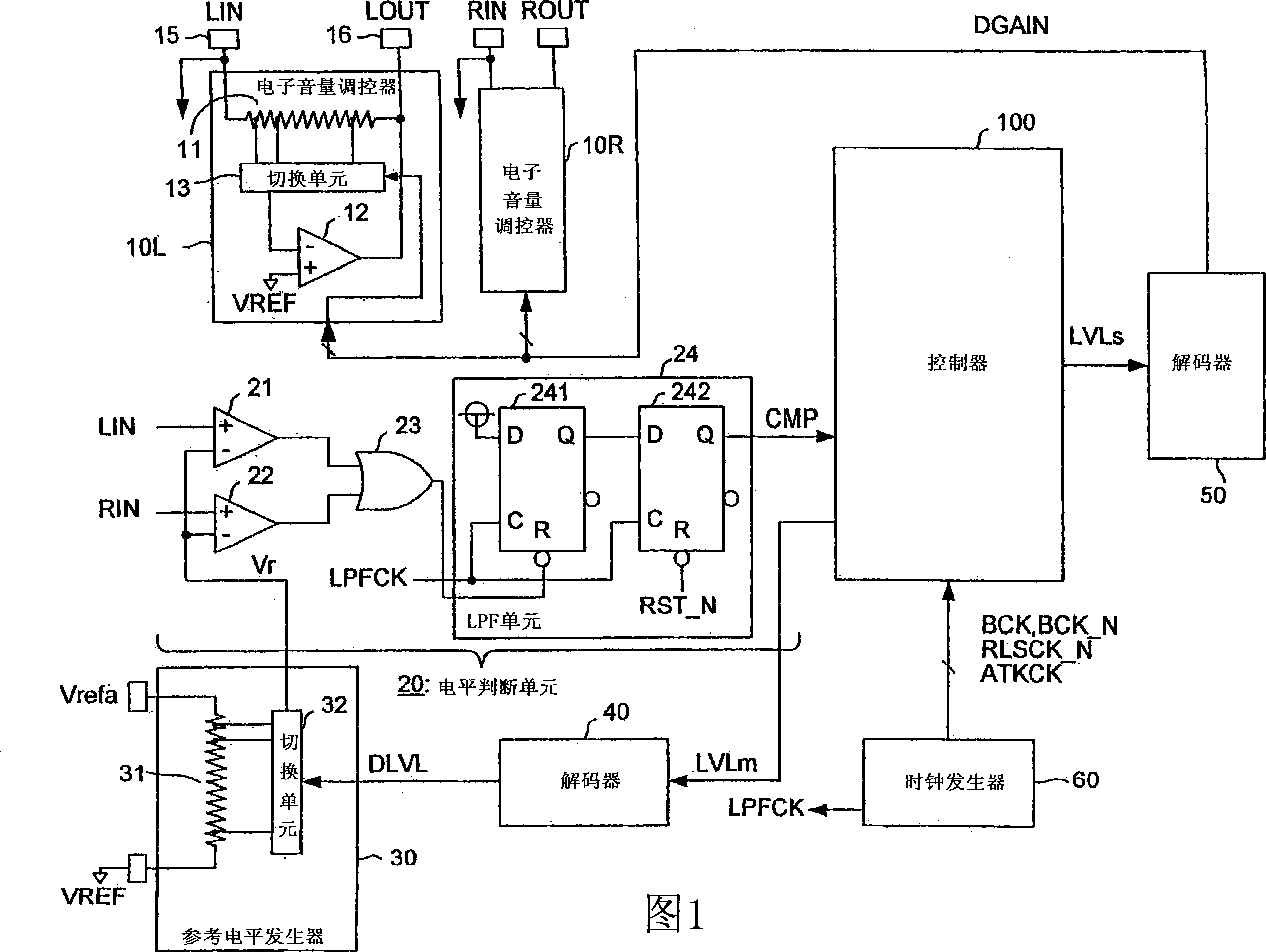
[0043] FIG. 1 is a block diagram showing the arrangement of an AGC (Automatic Gain Control) circuit according to a first embodiment of the present invention. The AGC circuit according to the first embodiment is a semiconductor integrated circuit in which the electronic faders 10L and 10R, the level judging unit 20, the reference level generator 30, the decoders 40 and 50, the clock generator are formed on a semiconductor substrate. 60, and the controller 100. The AGC circuit is mounted, for example, on an audio device such as a speaker playback device.

[0044] The electronic faders 10L and 10R are circuits that respectively amplify the L channel input audio signal LIN and the R channel input audio signal RIN based on the gain specifying data DGAIN, and output an audio signal LOUT and another audio signal ROUT. The gain designation data DGAIN is used in "N" kinds of gains G(K) (K=1 to N) from the decoder 50, and the magnitude relationship is given as G(1)>G(2)>, . . . G( N)....


PUM


Abstract

A controller 100 updates data LVLm indicative of a level section of an input audio signal and controls a reference level Vr based on a signal CMP representative of a comparison result between the input audio signal and the reference level Vr, and further, controls gains of electronic volumes 10L and 10R in such a manner that these gains become such gains corresponding to the level section of the input audio signal. In this case, the level sections of the input audio signals are related to the gains in such a manner that levels of output signals of the electronic volumes do not exceed a previously set output amplitude upper limit level.

Description

technical field [0001] The present invention relates to an automatic gain control circuit suitable for controlling the gain of audio equipment. Background technique [0002] Generally, in an output stage of audio equipment such as speaker playback equipment and recording equipment, an automatic gain control circuit (hereinafter referred to as "AGC circuit") is provided on a previous stage of a power amplifier. The above-mentioned AGC circuit is equipped with a function that can control the gain when the input audio signal is amplified so that the input signal is amplified at an appropriate level in the case where the waveform peak level of the input audio signal varies, and then will have an appropriate level. A flat amplified input audio signal is provided to the power amplifier. There is some possibility of using such an AGC circuit as a means for avoiding the occurrence of clipping in power amplifiers used in output stages of audio equipment. It should be understood tha...

Claims


Application Information

Patent Timeline
Patent Type & Authority Applications(China)
IPC IPC(8): H03G3/20
Inventor 田中泰臣辻信昭川合博贤
Owner YAMAHA CORP
Why Eureka
Try Eureka