Three-dimensional glass porous media model for microcosmic oil drive and manufacturing method thereof

A three-dimensional glass and porous media technology, applied in earth-moving drilling, production of fluids, wellbore/well components, etc., can solve the problem of not being able to ensure high-fidelity oil displacement process at the same time, and achieve high-fidelity effects

Inactive Publication Date: 2008-01-16
DAQING GASOLINEEUM INST
View PDF0 Cites 46 Cited by
  • Summary
  • Abstract
  • Description
  • Claims
  • Application Information

AI Technical Summary

Problems solved by technology

[0003] In order to solve the problem that the existing core model for microcosmic oil displacement cannot ensure a high degree of simulation and the visibility of the entire oil displacement process at the same time, the present invention provides a three-dimensional glass porous medium model for microcosmic oil displacement and a specially manufactured The method of this model, after applying this model, no

Method used


Image

  • Three-dimensional glass porous media model for microcosmic oil drive and manufacturing method thereof
  • Three-dimensional glass porous media model for microcosmic oil drive and manufacturing method thereof
  • Three-dimensional glass porous media model for microcosmic oil drive and manufacturing method thereof

Examples


Embodiment 1

[0045] The glass sheet for making the substrate adopts the PYREX 7740 type glass produced by Corning Corporation of the United States.

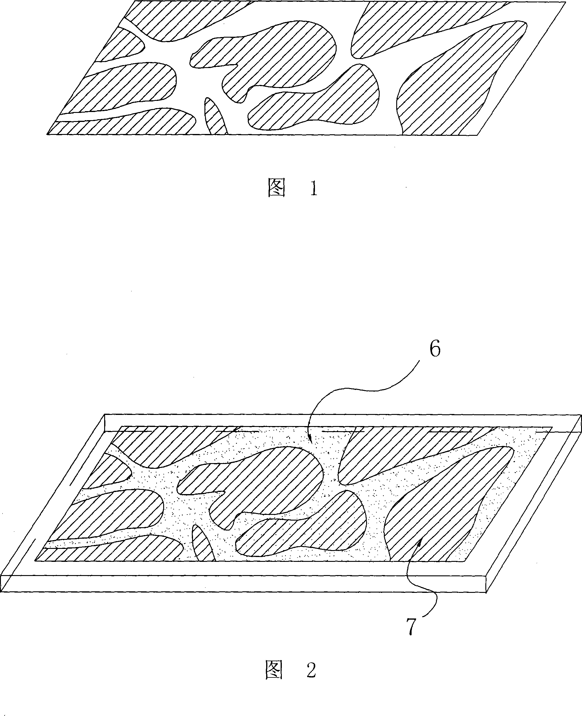
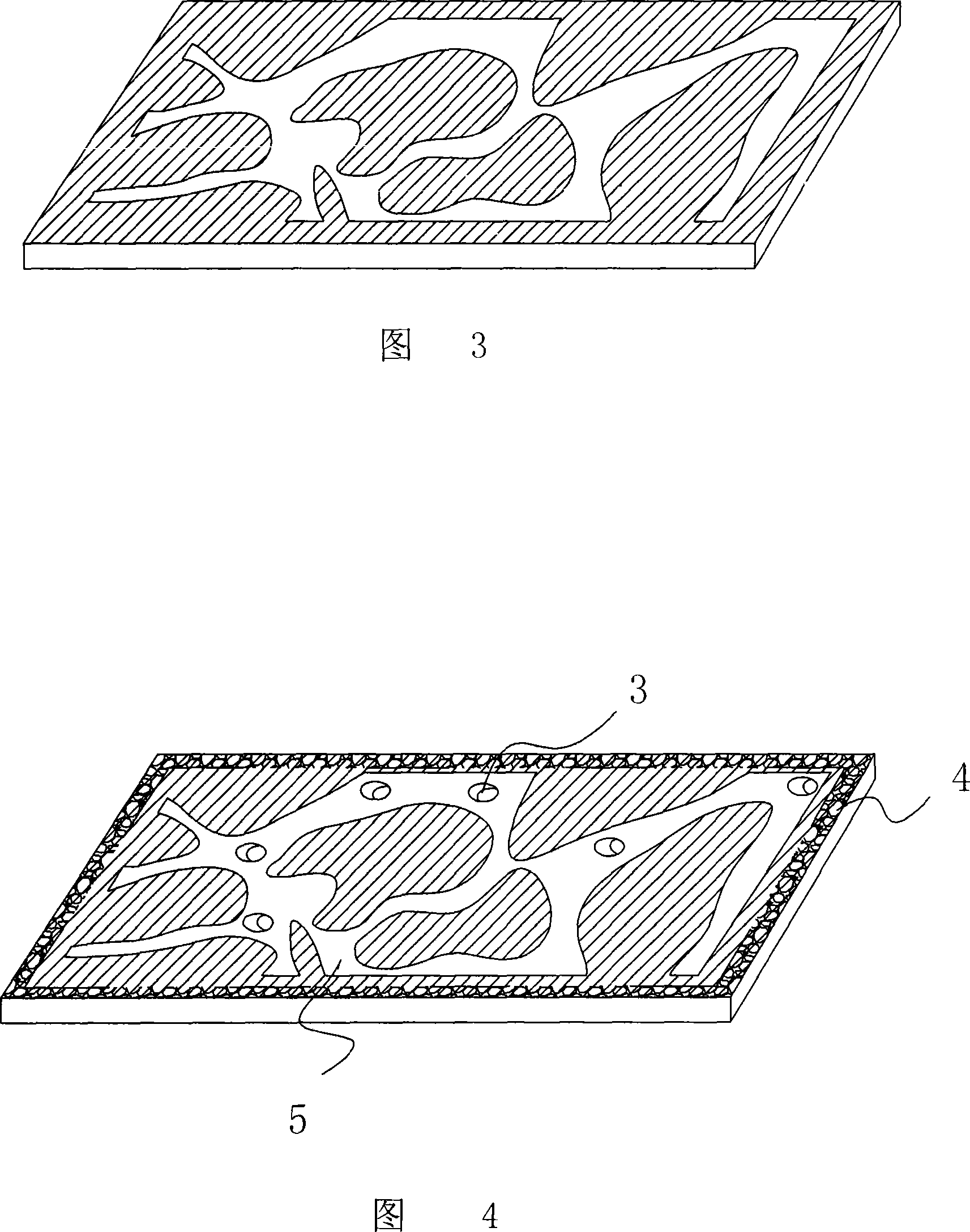
[0046] First, a mask is established on the surface of the glass sheet, and then the planar pore channels of the core are etched on the surface of the glass sheet according to the planar pore image of the natural core obtained by coring.

[0047] The process of creating a mask is:

[0048] (1) cleaning. The polished glass was ultrasonically cleaned with acetone and alcohol for 5 minutes, then soaked in potassium dichromate for one day to remove the oil on the surface, rinsed with deionized water, and dried with nitrogen flow.

[0049] (2) drying. Dry the cleaned glass piece in an oven at 130°C for one hour to enhance the surface activity of the glass.

[0050] (3) Double-sided coating. The dried glass sheet is plated with a 120 nm thick chromium film on both sides.

[0051] (4) Coat BP-212 type photoresist on both sides of the glass sheet...

Embodiment 2

[0062] The glass sheet for making the model adopts the PYREX 7740 type glass produced by Corning Corporation of the United States.

[0063] Firstly, a mask is established on the glass surface. The process flow is: (1) Cleaning, ultrasonically clean the polished glass with acetone and alcohol for 5 minutes, then soak it in potassium dichromate for one day to remove the oil on the surface, and then use deionized Rinse with water and blow dry with a stream of nitrogen. (2) Drying, the glass is dried in an oven at 130° C. for one hour to enhance the surface activity of the glass. (3) Double-sided coating, each of the two sides of the glass is coated with a chrome film with a thickness of 120nm. (4) Glue coating on both sides, using BP-212 photoresist, the speed of spinning the glue is 1500r / min, the throwing time of glue is 30s, and the thickness of the glue is about 2 microns. (5) Pre-baking, pre-baking in a thermostat at 90°C for 15 minutes. (6) Single-sided photolithography,...


PUM


Abstract

A 3D glass porous medium model for microscopic oil displacement is provided. The invention mainly solves the problem of the existing rock core model for microscopic oil displacement can not simultaneously assure high simulation degree and 3D visibility during the whole oil displacement process when conducting microscopic oil displacement experiment. The invention is characterized in that the model is formed by tightly bonding of at least three substrates made of glass material, a rock core planar pore channel (5) is respectively etched on the upper surface of a bottom substrate (12) and intermediate substrates (9, 10, 11), a plurality of throat channels (3) passing through the substrate are opened at a plurality of large apertures of the intermediate substrates (9, 10, 11), and a liquid injection channel (1) and a liquid outflow channel (2) are disposed on the model and respectively communicated with the large rock core planar pore channels (5) on the bottom substrate (12) and the first intermediate substrate (9). The invention can perform accurate 3D simulation of the rock core pore and assure high simulation degree during experiment, and the whole process is visible.

Description

Technical field: [0001] The invention relates to a porous medium model for simulating rock cores and a manufacturing method of the model, in particular to a porous medium model and a manufacturing method for completing microscopic oil displacement tests in an oil field. Background technique: [0002] The limitation of petroleum resources and its important role in economic development have increasingly become an important restrictive factor for the economic development of various countries. At present, most oilfields in my country have entered the late stage of high water cut development, and most of them have begun to use polymer flooding. In most cases, engineers and technicians need to pre-estimate the recovery factor of polymer flooding, determine the oil displacement mechanism of various oil displacement methods and understand the driving process of oil, gas, water and other fluids. Because this kind of estimation is usually carried out under the condition of not actual...

Claims


Application Information

Patent Timeline
IPC IPC(8): E21B43/16
Inventor 宋考平张继成张涛夏惠芬
Owner DAQING GASOLINEEUM INST
Why Eureka
Try Eureka