Simulation device of robot system

A robot system and simulation device technology, applied in the field of simulation devices, can solve problems such as many operations, low efficiency, and multi-operation man-hours

Inactive Publication Date: 2008-01-16
FANUC LTD
View PDF1 Cites 26 Cited by
  • Summary
  • Abstract
  • Description
  • Claims
  • Application Information

AI Technical Summary

Problems solved by technology

However, it is difficult for unfamiliar operators to adjust and determine the installation position of the camera or the setting of the detection parameters of the detection target because special knowledge is required.
In addition, since the position setting of the camera and the adjustment of the detection parameters of the detection target are performed by trial and error, a lot of man-hours are required.
Furthermore, since the setting position of the camera or the adjustment and confirmation of the detection parameters are actually carried out using equipment such as the detection target or the camera, a lot of work time is required.
In addition, when using the measurement results of the workpiece position by the visual recognition device to correct the movement of the robot, the confirmation of whether the measurement program and the operation program are appropriate is also carried out using the robot system together with the actual image processing device or control equipment. Lots of work, low efficiency

Method used


Image

  • Simulation device of robot system
  • Simulation device of robot system
  • Simulation device of robot system

Examples


Embodiment Construction

[0020] An embodiment of the simulator 30 of the robot system 10 of the present invention will be described below with reference to the drawings.

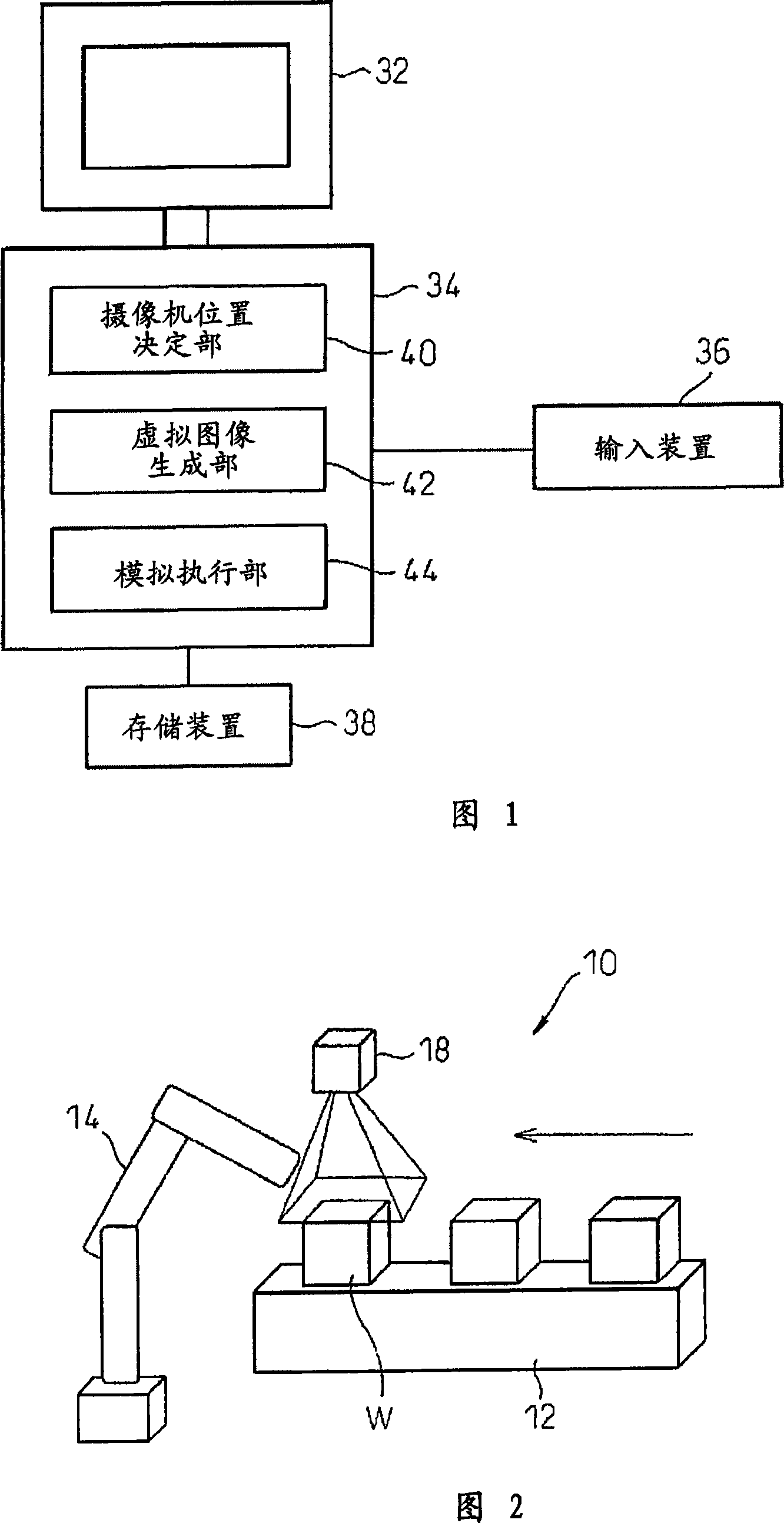
[0021] First, an example of the robot system 10 simulated by the simulation device 30 of the present invention will be described with reference to FIG. 2 . The robot system 10 has: a conveying device 12 for conveying a workpiece W as a work object, a robot 14 for performing predetermined processing such as a gripping action on the workpiece W conveyed to a predetermined position by the conveying device 12, and a robot 14 for detecting or measuring A visual recognition device 16 for the position of the workpiece W or a specific part thereof. As the conveying device 12, suitable conveying devices such as a conveying belt or a conveying roller can be used. Any type can be used for the robot 14, and it is not particularly limited.

[0022] The visual recognition device 16 is constituted by a camera 18 for obtaining an image, and an im...


PUM


Abstract

A simulation device displays a three-dimensional model of a robot system on a display device and simulates a robot system including a robot and an image pickup camera. The simulation device includes a display device for displaying a three-dimensional virtual space on a screen, a camera position determination unit for determining an installation position of the image pickup camera based on an image pickup range designated by the operator, optical characteristic information of the used image pickup camera, and required measurement precision, and a virtual image generator unit for generating a virtual image to be obtained by the image pickup camera based on the position of the image pickup camera in the three-dimensional virtual space and the optical characteristic information, thereby facilitating the determination of the suitable position of the image pickup camera and adjustment of the detection parameters.

Description

technical field [0001] The invention relates to a simulation device for offline simulation of robot systems. Background technique [0002] In a robot system, a workpiece is generally recognized by a visual recognition device, and processing specified in the robot is performed corresponding to the position of the recognized workpiece. For example, Japanese Unexamined Patent Publication No. 8-167800 discloses component mounting in which a mark on a component is irradiated with light, the reflected light or transmitted light is detected by a visual recognition device to identify the component, and a predetermined process is performed on the component. device. [0003] In a robot system using such a visual recognition device, it is necessary to adjust the installation position of the camera that determines the visual recognition device, the detection parameters of the detection target, and the like so as to obtain the required measurement accuracy. However, since special knowl...

Claims


Application Information

Patent Timeline
Patent Type & Authority Applications(China)
IPC IPC(8): G06F3/01G05B17/02G05B19/00
CPCB25J9/1671G05B19/4069G05B2219/40314G05B2219/39031G05B2219/32351Y02P90/02
Inventor 长塚嘉治武田俊也
Owner FANUC LTD
Why Eureka
Try Eureka