Foreset control device

A technology of control device and working face, which is applied to mine roof support, mining equipment, earthwork drilling and other directions, can solve the problems of increasing the failure probability of system components, complicated communication costs, and many system components, etc., and achieves convenient installation and operation. Improve the working environment and prevent damage

Active Publication Date: 2008-01-23
BEIJING TIANMA INTELLIGENT CONTROL TECH CO LTD
View PDF0 Cites 29 Cited by
  • Summary
  • Abstract
  • Description
  • Claims
  • Application Information

AI Technical Summary

Problems solved by technology

The disadvantage is that there are many system components and need to communicate with each other, which increases the

Method used


Image

  • Foreset control device
  • Foreset control device
  • Foreset control device

Examples


Embodiment 1

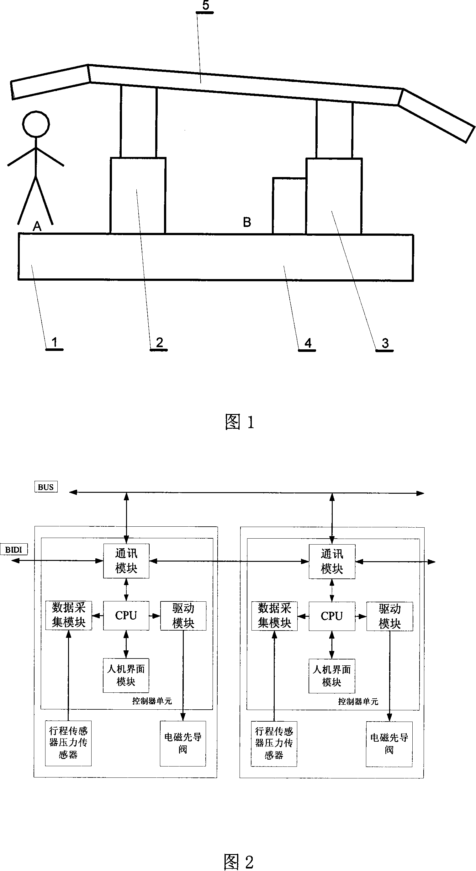
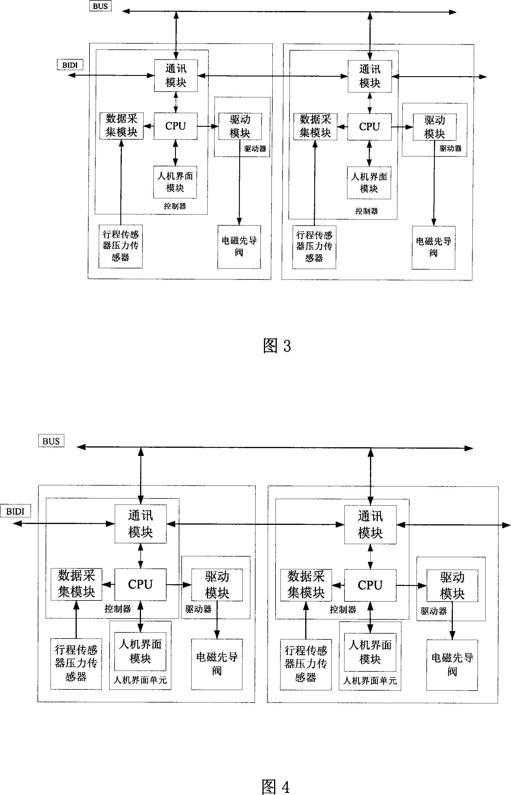
[0026] Fig. 5 is the schematic diagram of the principle of separation of each module of the present embodiment, what draw in the figure is only the functional block diagram of two support controllers, actually can have many support controllers it is connected together, and wherein a support controller comprises: and stroke The data acquisition module connected to the pressure sensor, the CPU, the communication module connected with other brackets through the CAN bus, the drive module connected with the electromagnetic pilot valve, and the man-machine interface module, the data acquisition module, the communication module, the CPU, and the drive module are composed control unit, the control unit is mounted on a controller printed circuit board, and the controller printed circuit board is sealed in the controller box housing; the man-machine interface module forms a man-machine interface unit, and the man-machine interface module The machine interface unit is installed on a man-m...

Embodiment 2

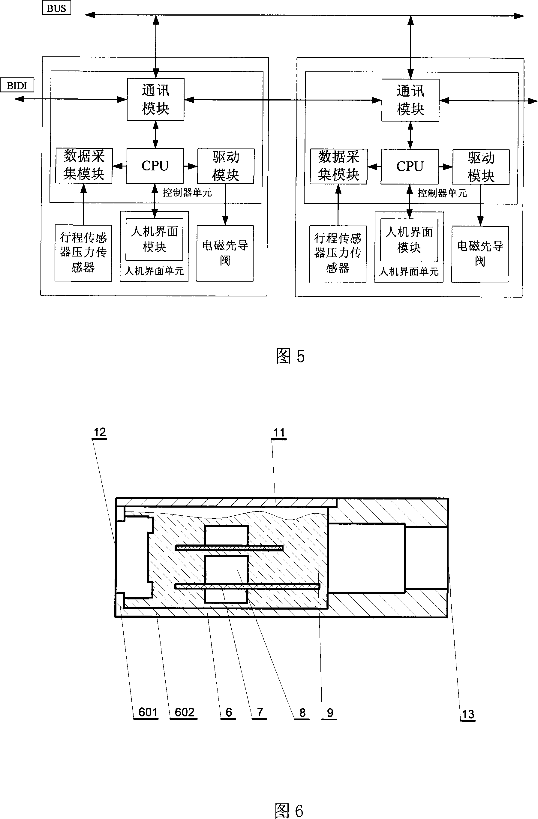
[0051] This embodiment is a preferred solution of the controller box of the bracket control device. The controller box shell is a metal rectangular box body 6, and the box body is welded and combined with a bottom surface 602 on the four sides 601 to form a Bathtub type, as shown in Figure 6. The purpose of this kind of production is to facilitate sealing, so that the overall performance of the box body is better, and it is not afraid of bumping, beating, and impact, and can protect the electronic components in the box to the greatest extent. A box cover 11 adapted to the shape and size of the box body is arranged, and the box cover is fixed on the box body with screws. The printed circuit board 7 on which the controller welds electronic components 8 is installed in the box, and the circuit board is fixed in the box by screws. The box is filled with sealant 9 , and the filling height of the sealant exceeds the height of the electronic components, so that the electronic compon...

Embodiment 3

[0053] This embodiment is an arrangement method of a cable socket of a bracket control unit. The shape of the bracket control unit is a rectangular box, as shown in FIG. . One side of the box is configured as the rear side 12 with 8 solenoid valve cable sockets connected to the drive module, as shown in FIG. 9 . The front side 13, as shown in Figure 10, is equipped with two 4-core cable sockets connected to the communication module to communicate with the left and right adjacent frames, one 4-core cable socket connected to the CPU to communicate with the human-machine interface unit, and one A 4-core cable socket connected to the data acquisition module and the travel sensor, two 4-core cable sockets for the pressure sensor connected to the data acquisition module, and a 4-core cable socket for the position monitoring sensor connected to the data acquisition module.

[0054] The rear side of the controller box is equipped with 8 solenoid valve cable sockets, which can be conn...


PUM


Abstract

The invention relates to a controlling apparatus for the support of a working face, is an electronic controller for a hydraulic support of a fully mechanized mining face in a coal mine pit. The invention comprises: a data acquiring module connected with a travel pressure sensor, a CPU, a communication module communicated with other supports through a CAN bus, a drive module connected with a solenoid pilot valve, and a man-machine interfacing module. The data acquiring module, the communication module, the CPU and the drive module form a control unit, which is sealed in the casing of the controller box. The man-machine interfacing module forms a man-machine interfacing unit, which is sealed in the casing of the controller box. The control unit is connected with the man-machine interfacing unit through a communication cable. Any quick-wearable part with low reliability in the support controller is removed, the reliability of the support controller is improved, also the working environment of the quick-wearable part in the support controlling unit is improved, and the impact of the quick-wearable part on the control system is reduced.

Description

technical field [0001] The invention relates to a working face support control device, which is an electronic device, a control device for a hydraulic support on a fully mechanized mining working face in a coal mine, and a control device for controlling the action of a hydraulic support and interacting with other hydraulic supports. The electronic device connected by the bracket. Background technique [0002] The hydraulic support is an important equipment for underground mining. As shown in Figure 1, a schematic diagram of a hydraulic support mainly includes two pairs of powerful hydraulic cylinders, the front row hydraulic cylinder 2 and the rear row hydraulic cylinder 3, which are installed on the base 1. The top plate 3 is pushed up to play the role of supporting the working surface. As shown in the figure, the height of the front hydraulic cylinder is relatively high, so it is more convenient for personnel to move around at position A, but the danger at position A is a...

Claims


Application Information

Patent Timeline
IPC IPC(8): E21D23/12
Inventor 张良张龙涛牛剑峰
Owner BEIJING TIANMA INTELLIGENT CONTROL TECH CO LTD
Why Eureka
Try Eureka