
Hermetic refrigerant compressor

A refrigerant and compressor technology, applied in mechanical equipment, machines/engines, liquid variable capacity machinery, etc., can solve problems such as reduction, and achieve the effect of reducing flow loss and small pressure difference

Active Publication Date: 2008-01-23
ACC AUSTRIA GMBH
View PDF1 Cites 5 Cited by
  • Summary
  • Abstract
  • Description
  • Claims
  • Application Information

AI Technical Summary

Problems solved by technology

All these known attempts to prevent the cold refrigerant coming from the evaporator from mixing with the hot refrigerant inside the compressor casing only contributed to a reduction in this mixing, but did not stop it completely.

Method used


Image

  • Hermetic refrigerant compressor
  • Hermetic refrigerant compressor
  • Hermetic refrigerant compressor

Examples


Embodiment Construction

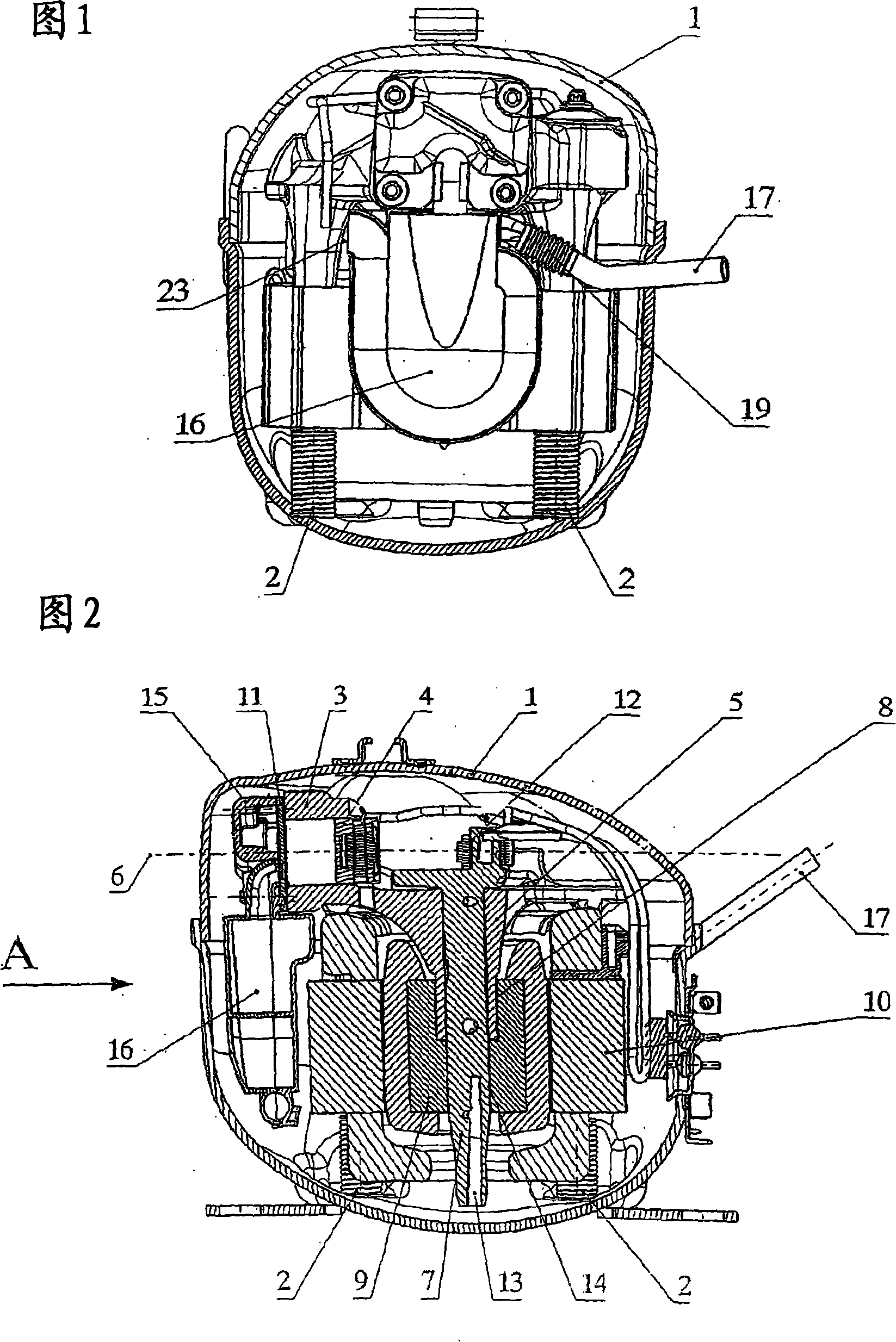
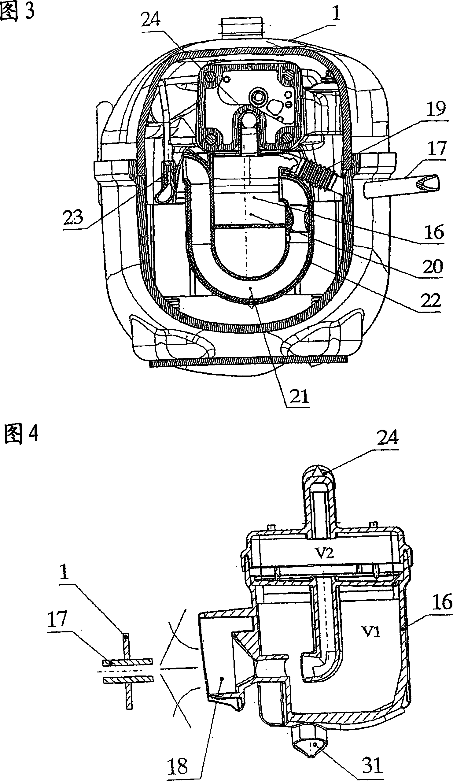
[0048] 1, 2 and 3 respectively show a sectional view of a hermetically sealed refrigerant compressor, wherein Figs. 1 and 3 respectively show views along the direction of arrow A in Fig. 2 . A piston cylinder motor unit is elastically supported by springs 2 inside the hermetically closed compressor housing 1 .

[0049] The piston working cylinder motor unit is mainly composed of a cylindrical housing 3 and a reciprocating piston 4 inside it, and a crank bearing 5, which is arranged perpendicular to the axis 6 of the working cylinder. The crankshaft bearing 5 supports a crankshaft 7 and projects into a central bore 8 of a rotor 9 of an electric motor 10 . At the upper end of the crankshaft 7 there is a connecting rod bearing 12 through which the connecting rod is driven and the piston 4 is further driven. The crankshaft 7 has a lubricating oil hole 13 and is fastened in a region 14 on the rotor 9 . The suction muffler 16 is arranged on the working cylinder head 15, and the su...


PUM


Abstract

The invention relates to a hermetically enclosed refrigerant compressor having a hermetically tight compressor housing inside of which a piston / cylinder unit that compresses a refrigerant operates with a suction valve having a suction opening located in a valve plate of the unit. A suction sound damper having a filling volume is provided on the cylinder head of the piston / cylinder unit and refrigerant flows to the suction valve of the piston / cylinder unit via this suction sound damper. To this end, the suction sound damper has an entry cross-section via which refrigerant flows into the suction sound damper, and a compensation volume is provided, which is connected to the suction sound damper and to the interior of the compressor housing, and inside of which refrigerant oscillates. The compensation volume equals 0.5 to 3 times the displacement of the piston of the piston / cylinder unit.

Description

technical field [0001] The invention relates to a hermetically sealed refrigerant compressor according to the preamble of claim 1, which has a hermetically sealed compressor housing in which a refrigerant-compressing piston-operating-cylinder unit works, in which A suction muffler (Muffler) is arranged on the working cylinder head, and the refrigerant flows through it to the suction valve of the piston working cylinder unit. Background technique [0002] Such refrigerant compressors have been known for a long time and are mainly used in refrigerators or freezers. Therefore, the annual output is very large. [0003] Although the energy consumption of a single refrigerant compressor is only about 50 to 150 watts, very high energy consumption is obtained when considering the refrigerant compressors used worldwide, which due to the rapid continuous development even in Energy consumption in poor countries is also increasing. [0004] Every technical improvement and efficiency ...

Claims


Application Information

Patent Timeline
IPC IPC(8): F04B39/00
CPCF04B39/0072F04B39/0061F04B39/123
Inventor H·P·舍格勒
Owner ACC AUSTRIA GMBH
Learn More