DC propulsion motor

A technology of electric motor and armature iron core, applied in the field of electric motor, can solve the problems such as the higher requirements of vibration and noise of quiet DC propulsion motor, the phase difference in the direction of radial electromagnetic force, large electromagnetic vibration and noise that cannot be well satisfied , to ensure the performance of single pivot operation, electromagnetic vibration suppression, low vibration and noise

Inactive Publication Date: 2008-01-30
中国船舶重工集团公司第七一二研究所
View PDF0 Cites 3 Cited by
  • Summary
  • Abstract
  • Description
  • Claims
  • Application Information

AI Technical Summary

Problems solved by technology

But at the same time, because each armature corresponds to the different positions of the teeth at both ends of the main magnetic pole of the stator, there is a phase difference in the direction of the radial electromagnetic force, which causes the corresponding part of the base housing to be torsion and bending at the same time, and the overall vibration of the base will be and when the natural frequency of the flexural vibration of the machine base is the same as or close to the frequency of the rotor teeth, it will cause greater electromagnetic vibration and noise. Therefore, this double-armature rotor form cannot well meet the needs of quiet DC propulsion motors. The higher requirements for vibration and noise also affect the realization of other technical indicators and normal operation of the propulsion motor
In the application of DC propulsion motors with strict requirements on vibration and noise, the "herringbone"-shaped armature winding can effectively reduce the radial electromagnetic force and improve the vibration and noise characteristics of the motor. However, due to the design and structure of the herringbone armature winding , winding insulation and technology are more complicated than traditional techniques, etc. Therefore, there has not been a DC propulsion motor with the technical solution of the present invention before the present invention

Method used


Image

  • DC propulsion motor
  • DC propulsion motor

Examples


Embodiment Construction

[0025] The present invention is further described as follows in conjunction with accompanying drawing and embodiment:

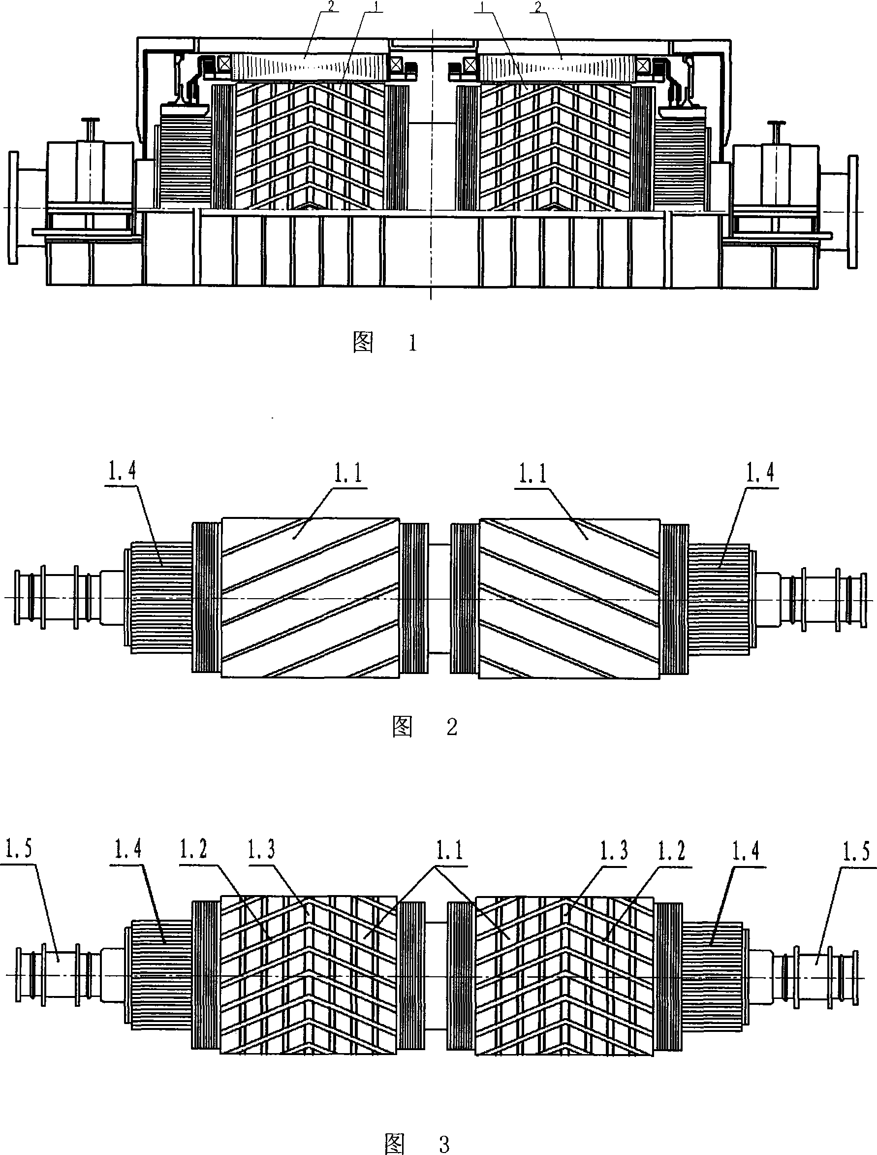
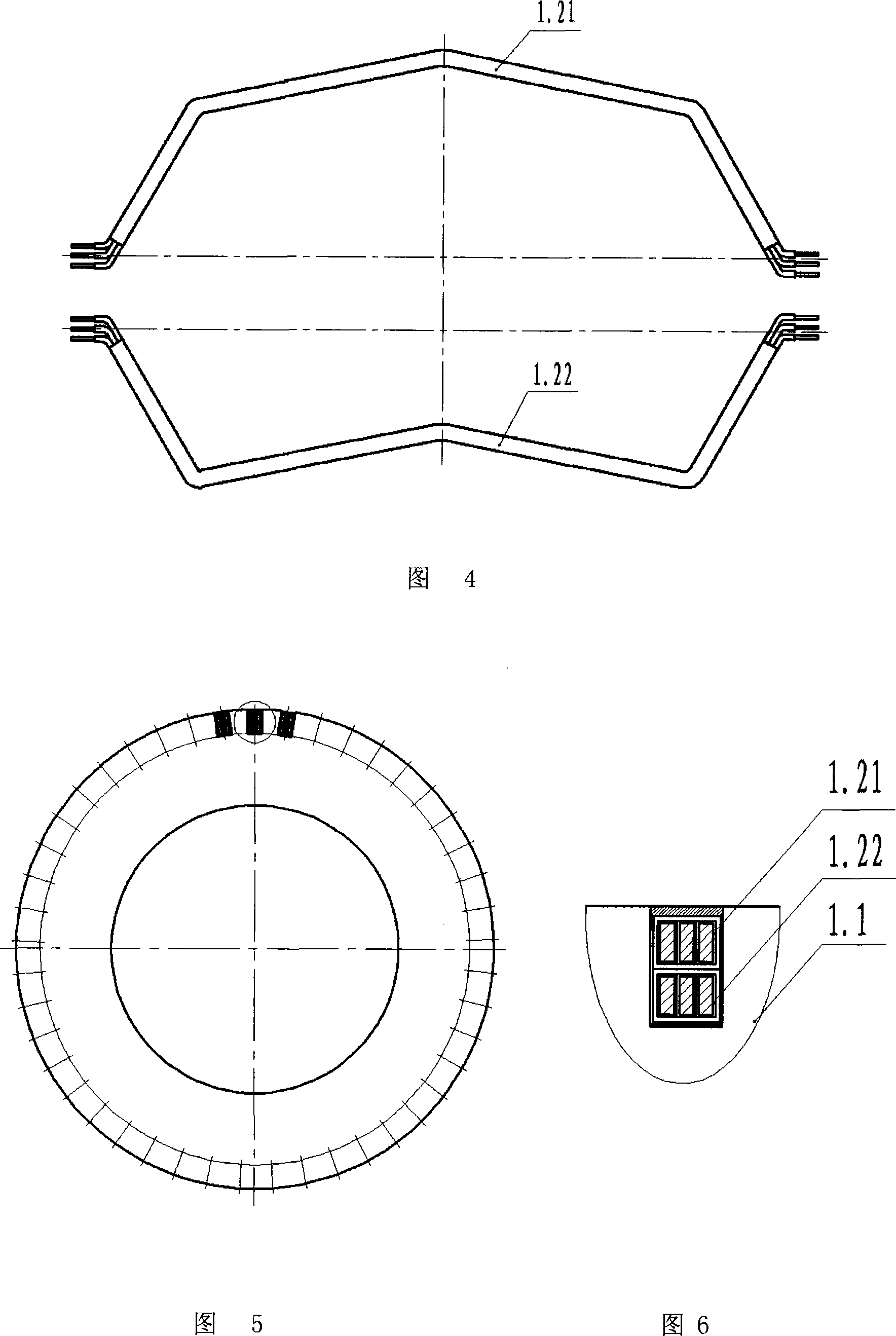
[0026] As shown in Figures 1, 3, 4, 5, and 6, it is a DC propulsion motor, which has a rotor 1 and a stator 2; the rotor 1 has an armature core 1.1, an armature winding 1.2, and a radial ventilation ditch 1.3, commutator 1.4, rotating shaft 1.5; the armature winding 1.2 distributed on the outer circumference of the armature core 1.1 is a "herringbone"-shaped winding; the "herringbone"-shaped armature winding 1.2 is insulated by a coil The "herringbone"-shaped upper coil 1.21 and the package-insulated "herringbone"-shaped lower coil 1.22 are divided into half structures, embedded in the "herringbone"-shaped chute of the armature core 1.1 (as shown in Figure 4, Figure 5, As shown in Figure 6), the size of the chute near the turning point is slightly larger than the size of the chute at the straight line; the "herringbone" shape of the armature winding 1.2, its ...


PUM


Abstract

The invention relates to a direct current propulsion motor which belongs to the field of motor technology, which is particularly suitable for the direct current propulsion motor which is used for medium vessel and large vessel. The invention comprises a rotor and a stator, wherein the rotor comprises an armature core, an armature winding, a radical ventilation duct, a commutator and a rotating shaft; the armature winding which is distributed on the external circumference surface of the armature core is inverted 'V'-shaped; the inverted 'V'-shaped armature winding consists of an inverted 'V'-shaped upper coil of winding insulation and an inverted 'V'-shaped lower coil of winding insulation which are both of half-style structure and are embedded into an inverted 'V'-shaped skewed slot of the armature core. The invention has the advantages that: the radial electromagnetic force of the motor is reduced; the amplitude and the vibration noise are reduced; the working environment is improved; the electromagnetic vibration of a whole motor base is reduced; the electromagnetic vibration in the whole speed range of the motor is assuredly promoted to be restricted to the greatest degree; the operation effect is better; and the function is much better exerted.

Description

technical field [0001] The invention relates to a DC propulsion motor, which belongs to the technical field of electric motors and is particularly suitable for use as a DC propulsion motor for medium and large ships. Background technique [0002] In the existing technology, in order to meet the specific requirements of medium and large DC propulsion motors for working conditions and environments, such as large marine DC propulsion motors, which have limited layout space and a large speed range, there is a technical measure to make double motors Pivot double commutator form. In order to reduce electromagnetic vibration and noise, the armature core adopts a unidirectional chute shape to reduce tooth harmonics. The direction of the chute of the armature core is opposite (as shown in Figure 2), and the armature winding adopts a single chute correspondingly. to tilt. But at the same time, because each armature corresponds to the different positions of the teeth at both ends of ...

Claims


Application Information

Patent Timeline
Patent Type & Authority Applications(China)
IPC IPC(8): H02K23/20H02K23/36
Inventor 谌瑾吴永铨文立辉祝后权
Owner 中国船舶重工集团公司第七一二研究所
Why Eureka
Try Eureka