Gain fluctuation regulation circuit and method

A technology of adjusting circuits and adjusting methods, applied in gain control, electrical components, impedance networks, etc., can solve the problems of insufficient system stability, deterioration, poor standing wave performance, etc., to improve the in-band fluctuation index, ensure normal operation, Guaranteed effect of linearity

Active Publication Date: 2008-02-06
AUCTUS TECH CO LTD
View PDF0 Cites 12 Cited by
  • Summary
  • Abstract
  • Description
  • Claims
  • Application Information

AI Technical Summary

Problems solved by technology

For high-power amplifier MOSFET tubes working in the 3G frequency band, the gain fluctuation is a more sensitive indicator, and it is particularly susceptible to being affected and deteriorated when the output power is high.
In addition, the differential loss of the devices in the circuit may also have large differences in different frequency bands
[0008] 2. Gain fluctuation and deterioration caused by debugging

Method used


Image

  • Gain fluctuation regulation circuit and method
  • Gain fluctuation regulation circuit and method
  • Gain fluctuation regulation circuit and method

Examples


Embodiment Construction

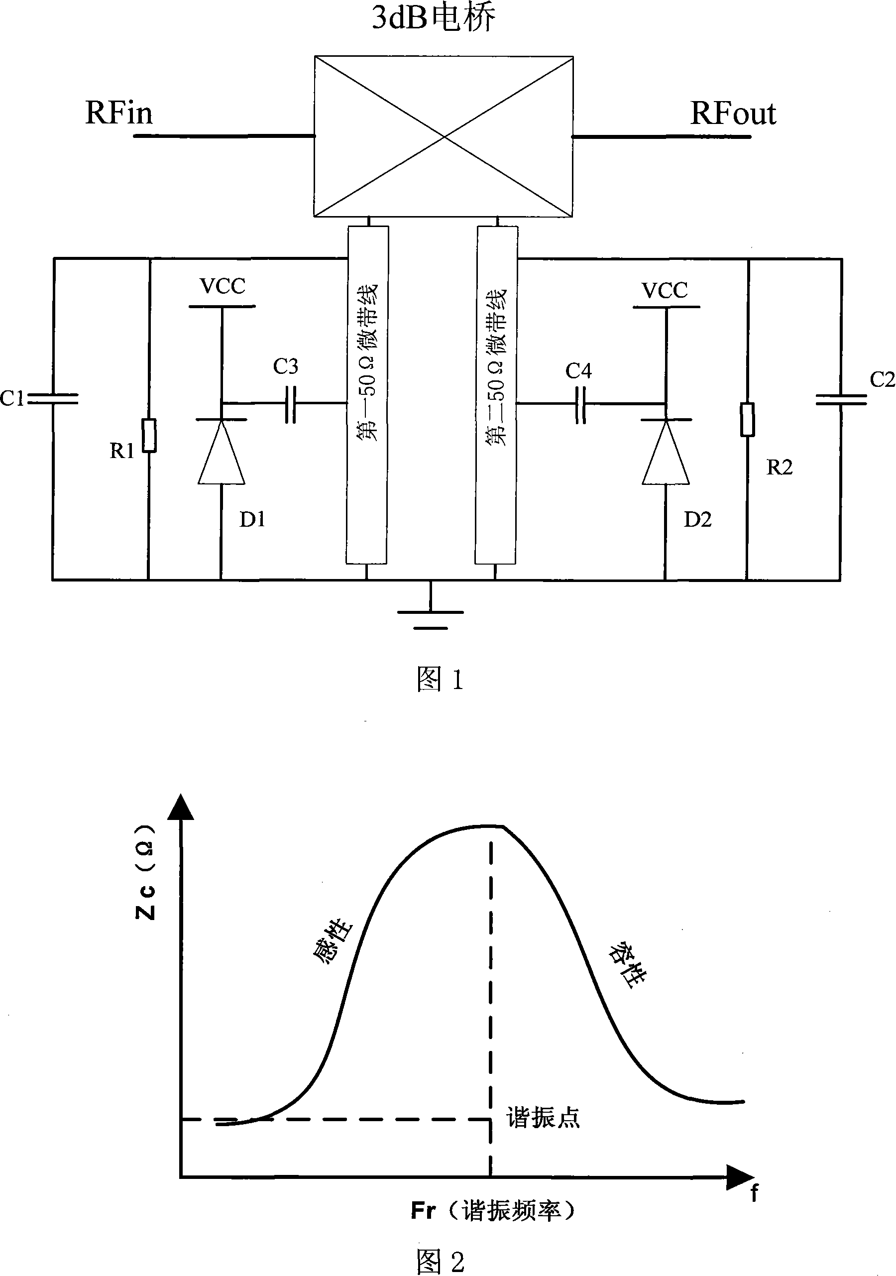
[0032] The gain fluctuation adjusting circuit of the present invention, its structure is shown in Figure 1, comprises

[0033] The first resonant circuit includes a first 50Ω microstrip line connected between the 90-degree phase end of a 3dB electric bridge and the ground, and the vicinity of one end connected to the 3dB electric bridge on the first 50Ω microstrip line is connected to the ground A capacitor C1 and a resistor R1 are connected in parallel therebetween, one end of a variable capacitor D1 is grounded, and a capacitor C3 is connected between the other end and the middle of the first 50Ω microstrip line;

[0034] The second resonant circuit includes a second 50Ω microstrip line connected between the 0-degree phase end of the 3dB electric bridge and ground, and the vicinity of one end connected to the 3dB electric bridge on the second 50Ω microstrip line and A capacitor C2 and a resistor R2 are connected in parallel between the grounds, one end of a variable capacito...


PUM


Abstract

The present invention discloses a gain fluctuation adjusting circuit which consists of a first resonance circuit that is connected with the 90 Dgr phase end of a 3dB bridge and a second resonance circuit that are connected with the 0 Dgr phase end of the 3dB bridge and both are connected in series. The present invention also discloses a gain fluctuation adjusting method, the signals are divided into two groups after entering the 3dB bridge and the two groups enter the first resonance circuit and the second resonance circuit respectively. The two resonance circuit processes the signals and return theses signals back to the 3dB bridge which reunify the two groups of signals and then sent out. The present invention can adjust the variable capacitance of the two resonance circuit so as to adjust the in-band gain fluctuation of the circuit. The present invention can compensate the inclination of the gain of the amplifier within the range of the frequency domain through changing the resonance point of the resonance circuit by adjusting the variable capacitance, which improves the index of the in-band wave and ensures linearity of the power amplifier and normal work. Furthermore, the present invention is convenient to be controlled and easy to be carried out with low cost.

Description

technical field [0001] The invention relates to a circuit, in particular to a gain fluctuation regulating circuit. The invention also relates to a gain fluctuation adjustment method. Background technique [0002] RF power amplifiers are widely used in the field of wireless communication. In recent years, with the increase of signal modulation methods, in order to meet the increasingly high efficiency and linearity requirements for power amplifiers, new designs such as multi-stage power amplifiers, feedforward technology and unbalanced amplification have been developed. Among these new power amplifier designs, Gain fluctuation technology is one of the key technologies. [0003] Gain fluctuation refers to the difference between the maximum and minimum levels within the effective working frequency band of the repeater, which is used to measure the gain fluctuation within the band. Usually, the requirement for in-band gain fluctuation will not exceed 3dB. If the gain fluctuat...

Claims


Application Information

Patent Timeline
IPC IPC(8): H03F1/00H03F1/32H03G3/20H03H7/00
Inventor 夏瑜夏天
Owner AUCTUS TECH CO LTD
Why Eureka
Try Eureka