Plant and method for liquefying natural gas

A technology for liquefied natural gas and natural gas, applied in liquefaction, refrigeration and liquefaction, lighting and heating equipment, etc., can solve problems such as increased pressure, reduced liquefaction efficiency, and complex equal distribution, and achieves the effect of simple method and increased overall efficiency

Inactive Publication Date: 2008-02-06
SHELL INT RES MAATSCHAPPIJ BV
View PDF5 Cites 2 Cited by
  • Summary
  • Abstract
  • Description
  • Claims
  • Application Information

AI Technical Summary

Problems solved by technology

[0003] A problem with the above described apparatus and methods is the possibility of uneven distribution, since the natural gas will usually be partially condensed in the pre-cooling cycle
Equal distribution of the partially condensed gas stream over the main liquefaction cycles arranged in parallel is complex and requires additional equipment and controls, resulting in increased pressure drop across the system and consequent reduction in liquefaction efficiency

Method used


Image

  • Plant and method for liquefying natural gas
  • Plant and method for liquefying natural gas
  • Plant and method for liquefying natural gas

Examples


Embodiment Construction

[0035] For descriptive purposes, a single reference number will be assigned to the pipeline and the natural gas stream conveyed in the pipeline. Like numbers refer to like parts.

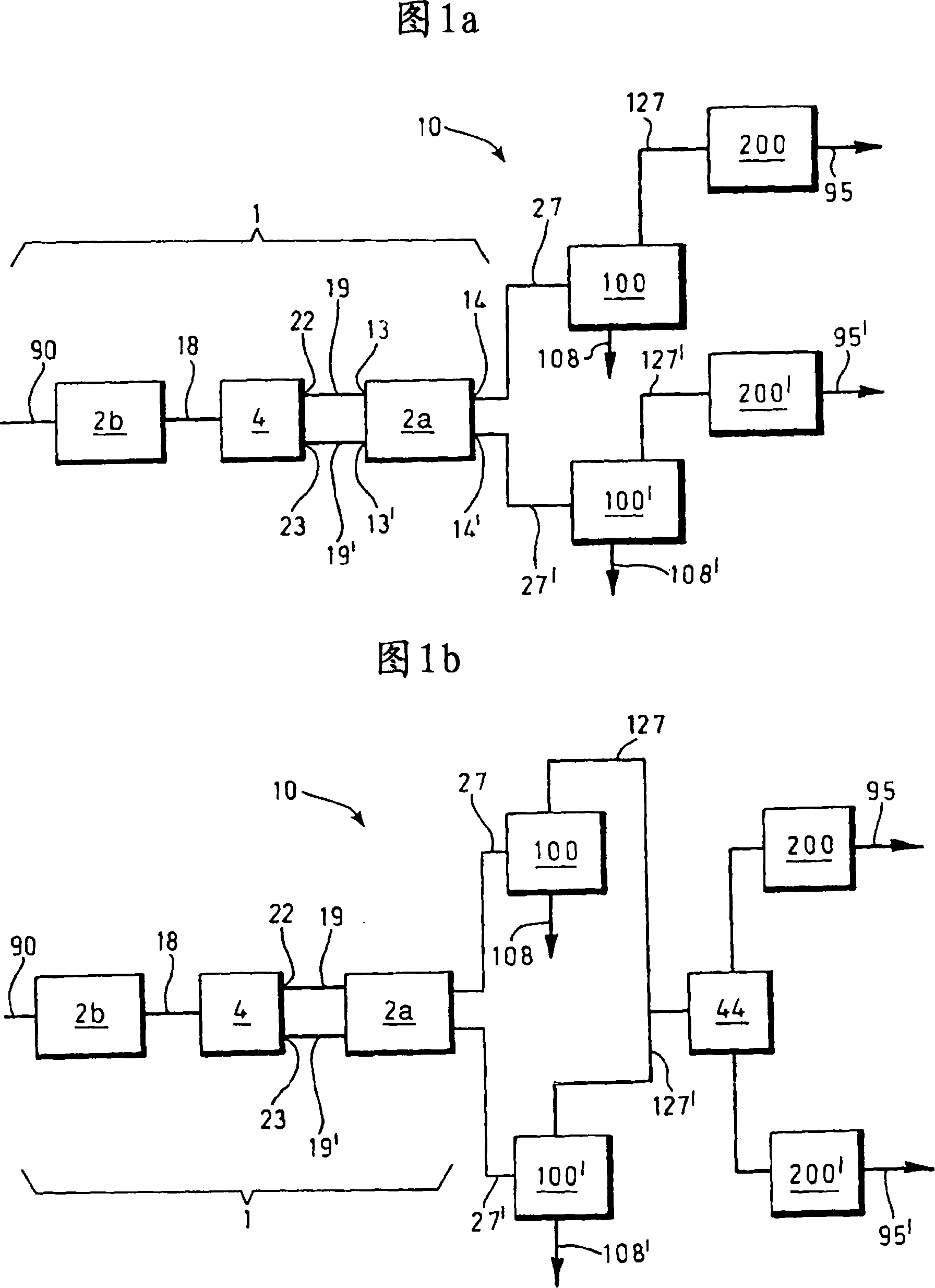
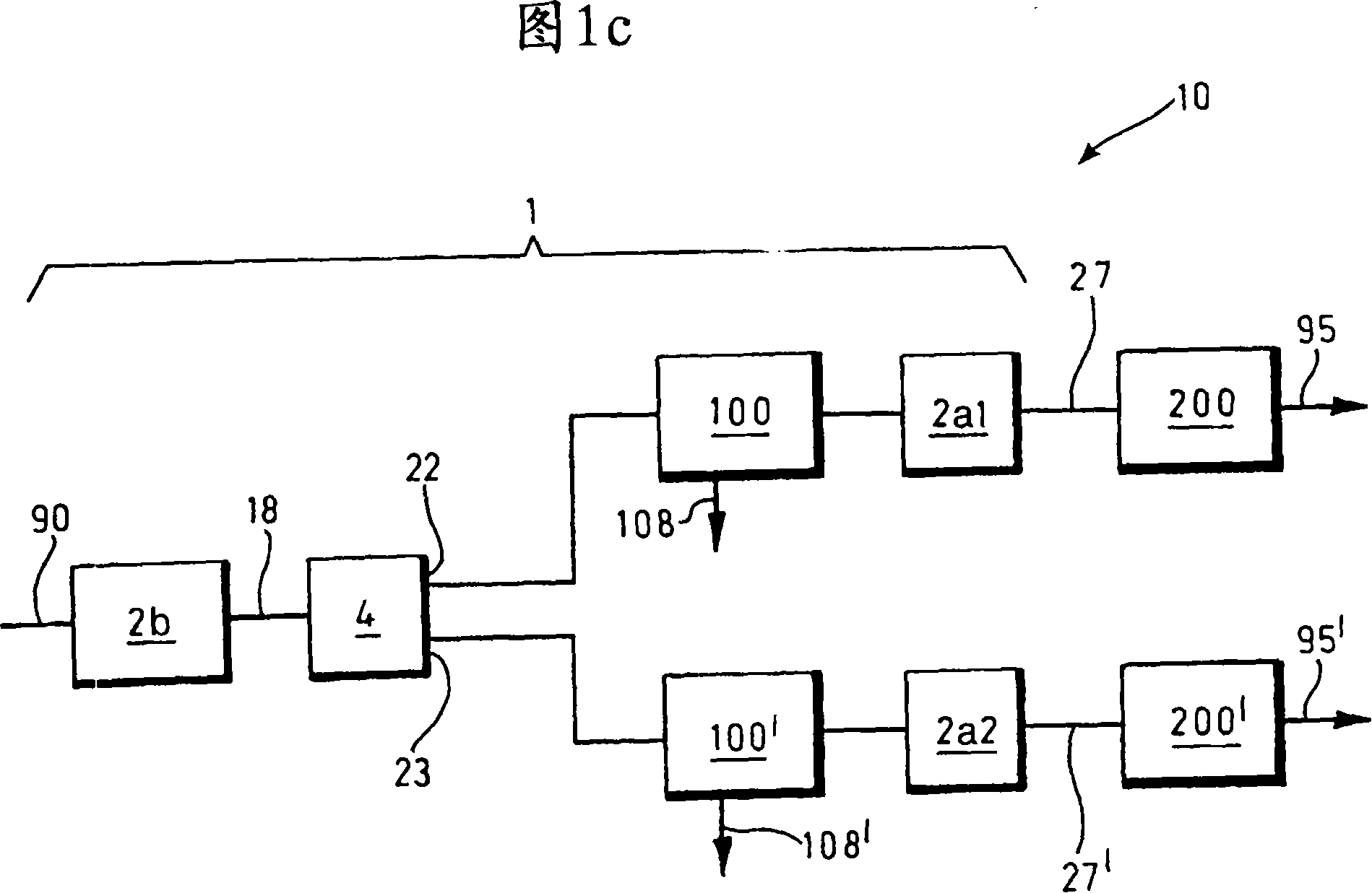
[0036] See Figures 1a-1c. The plant 10 for liquefaction of natural gas according to the invention comprises: a natural gas precooling heat exchanger chain 1, a distributor 4, two main cryogenic systems 200 and 200', and optionally two natural gas liquid extraction units 100 and 100'. The precooling heat exchanger chain 1 has an inlet line 90 for natural gas and outlet lines 27, 27' for precooled natural gas. In the embodiment shown in Figures 1a-1c, the pre-cooling heat exchanger chain 1 comprises two heat exchangers 2a, 2b, wherein the heat exchanger 2a is the final heat exchanger. Those skilled in the art will appreciate that the chain 1 may comprise more than two heat exchangers. If desired (and preferred), the heat exchangers of chain 1 can be part of the same refrigerant circuit.

[0037] T...


PUM


Abstract

The present invention relates to a plant (10) for liquefying natural gas (90) , the plant (10) at least comprising: - a pre-cooling heat exchanger train (1) comprising a final heat exchanger (2a) for cooling the natural gas stream (90); - a distributor (4) located upstream of the final heat exchanger for splitting the natural gas stream (90) into at least first and second natural gas substreams; - at least first and second main cryogenic systems (200,200') , each system (200,200') comprising an outlet for liquefied natural gas (95,95').

Description

technical field [0001] The present invention relates to apparatus and methods for liquefying natural gas. Background technique [0002] US Pat. No. 6,389,844 discloses such an apparatus and method. It consists of a single common pre-cooling cycle followed by two main liquefaction cycles arranged in parallel and operated simultaneously, in which the natural gas flowing through the plant is liquefied and subcooled. [0003] A problem with the above described apparatus and methods is the possible uneven distribution, since the natural gas will normally be partially condensed in the pre-cooling cycle. The equal distribution of the partially condensed gas stream over the main liquefaction cycles arranged in parallel is complicated and requires additional equipment and controls, resulting in increased pressure drop across the system and thus a reduction in liquefaction efficiency. Contents of the invention [0004] It is an object of the present invention to minimize the above...

Claims


Application Information

Patent Timeline
Patent Type & Authority Applications(China)
IPC IPC(8): F25J1/02
CPCF25J1/0042F25J1/0283F25J1/0216F25J1/004F25J1/0219F25J1/0292F25J1/0241F25J1/0052F25J2220/62F25J1/0268F25J1/0284F25J2230/60F25J1/0214F25J1/0055F25J2205/02F25J1/0287F25J1/0022F25J1/0265F25J1/0274F25J2220/64F25J2245/02F25J1/0295F25J1/0271F25J1/0238F25J1/02
Inventor J·M·范德赫拉夫
Owner SHELL INT RES MAATSCHAPPIJ BV
Why Eureka
Try Eureka