Fuel cell structure and method for manufacturing same

A technology of fuel cells and electrolyte membranes, which is applied in the direction of fuel cells, structural parts, battery electrodes, etc., and can solve problems such as insufficient improvement

Inactive Publication Date: 2008-02-06
堀胜 +2
View PDF1 Cites 2 Cited by
  • Summary
  • Abstract
  • Description
  • Claims
  • Application Information

AI Technical Summary

Problems solved by technology

But the improvem

Method used


Image

  • Fuel cell structure and method for manufacturing same
  • Fuel cell structure and method for manufacturing same
  • Fuel cell structure and method for manufacturing same

Examples


example 1

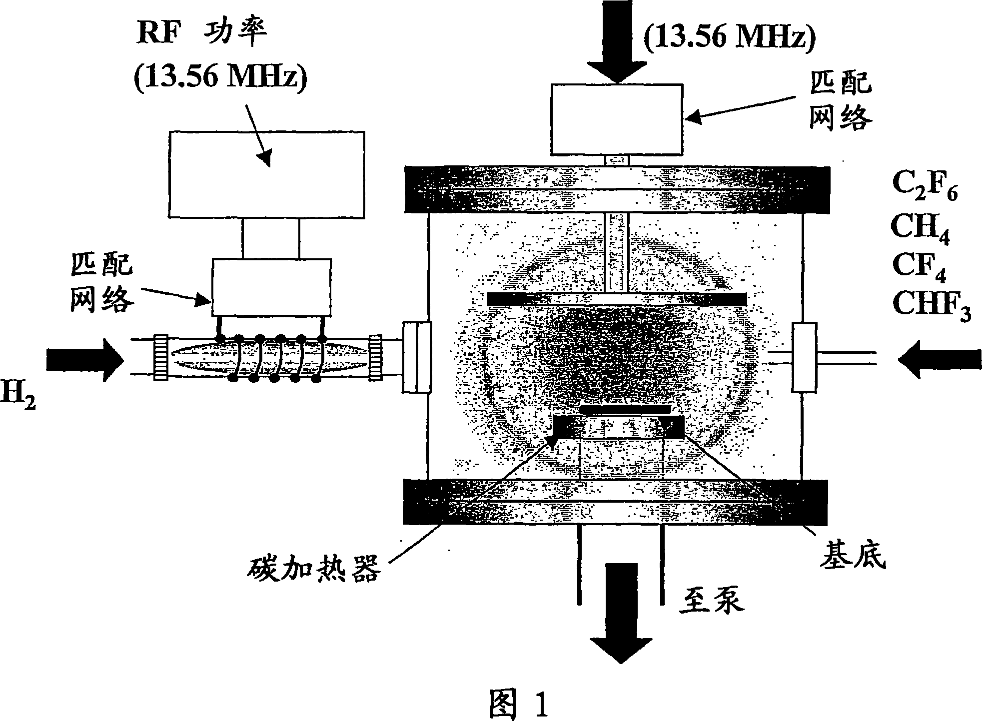
[0045] A device for manufacturing a diffusion layer-catalyst layer integrated thin film using the diffusion layer-catalyst layer one-step manufacturing method shown in FIG. 6 is described. In this example, CNW was used for the diffusion layer and the catalyst layer. First, using the plasma CVD apparatus shown in FIG. 6, CNW was produced on the spacer as a diffusion layer. Thereafter, the fabrication conditions were changed and CNWs were fabricated while modifying the surface of CNWs with catalyst components and electrolytes by laser, arc discharge, or plasma. In this way, the diffusion layer-catalyst layer integrated thin film is completed. Conversely, the catalyst layer and finally the diffusion layer can also be produced from the electrolyte side. The proton conductor is composed of substances with sulfonic acid groups, phosphoric acid groups, hydroxyl groups, imidazolyl groups, solid acid salts, cycloheptatrienol ketones, ionic liquids, etc. as proton carriers. Catalyst ...

example 2

[0047] FIG. 7 shows an example of a method of providing openings by plasma etching. In this method, metal nanoparticles are deposited on the surface of CNWs, eg by arc discharge or plasma discharge. In this case the amount deposited was such that the CNWs were visible. Thereafter, the CNWs are etched separately, providing nano-sized vias. For example, by exposing the CNW in FIG. 7 to oxygen plasma, etching is performed only in gap portions between metal particles, so that via holes can be formed in those portions.

[0048] According to Examples 1 and 2, the following advantages can be obtained: (1) since the diffusion layer-catalyst layer integrated thin film can be formed at one time in the same chamber, the number of steps can be reduced and thus the cost can be reduced; and (2) since the diffusion layer is continuously formed Layer - Catalyst layer, so there is no contact resistance, which can reduce the loss of power generation in the fuel cell.


PUM


Abstract

Disclosed is a fuel cell structure wherein a nanosized porous carbon material such as carbon nanowall (CNW) is used as a diffusion layer and/or a catalyst layer. Also disclosed is a method for manufacturing such a fuel cell structure. This fuel cell structure enables to simplify production process of an electrode for fuel cells which is composed of an electrode catalyst layer and a gas diffusion layer, while increasing conductivity of the catalyst layer and improving diffusion efficiency of the diffusion layer. Consequently, there can be obtained a fuel cell which is improved in power generation efficiency.

Description

technical field [0001] The invention relates to a polymer dielectric fuel cell structure and a manufacturing method thereof, which can simplify the manufacturing process and reduce the amount of catalyst precious metals, thus greatly reducing the cost. Background technique [0002] There are various types of fuel cells depending on the type of electrolyte used, such as polymers, phosphoric acid, solid oxides, molten carbonates, and alkalis. Among these fuel cells, the polymer electrolyte fuel cell operates at a lower temperature and has a shorter start-up time than other types of fuel cells. It is also easier to produce high output, desired size and weight reduction and shock resistance. For these reasons, polymer electrolyte fuel cells are suitable as a power source for moving objects. [0003] Fuel cells usually use perfluorosulfonic acid with high proton conductivity. Examples of ion exchange membranes currently used in polymer electrolyte fuel cells include perfluoroc...

Claims


Application Information

Patent Timeline
IPC IPC(8): H01M4/96H01M4/88
CPCY02E60/50H01M8/0234H01M4/96H01M4/8867H01M4/8817Y02P70/50
Inventor 堀胜平松美根男加纳浩之吉田怜片山幸久杉山彻
Owner 堀胜
Why Eureka
Try Eureka