Method for processing strong exothermal reaction using with constant-temperature heat exchanging device

An exothermic reaction and heat exchange device technology, applied in the direction of heat exchanger types, indirect heat exchangers, chemical instruments and methods, etc., can solve the problems of catalyst burnout, small heat capacity, and lack of heat exchange. The effect of improving efficiency

Active Publication Date: 2008-02-20
BC P INC CHINA NAT PETROLEUM CORP +1
View PDF0 Cites 6 Cited by
  • Summary
  • Abstract
  • Description
  • Claims
  • Application Information

AI Technical Summary

Problems solved by technology

In the traditional bottom-up countercurrent cycle, the temperature of the circulating medium at the inlet is low, and the temperature at the outlet rises, which is consistent with the change in the heat of reaction. Therefore, sufficient heat exchange i

Method used


Image

  • Method for processing strong exothermal reaction using with constant-temperature heat exchanging device
  • Method for processing strong exothermal reaction using with constant-temperature heat exchanging device
  • Method for processing strong exothermal reaction using with constant-temperature heat exchanging device

Examples


Embodiment 1

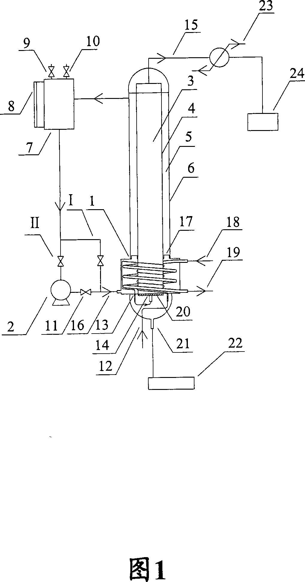
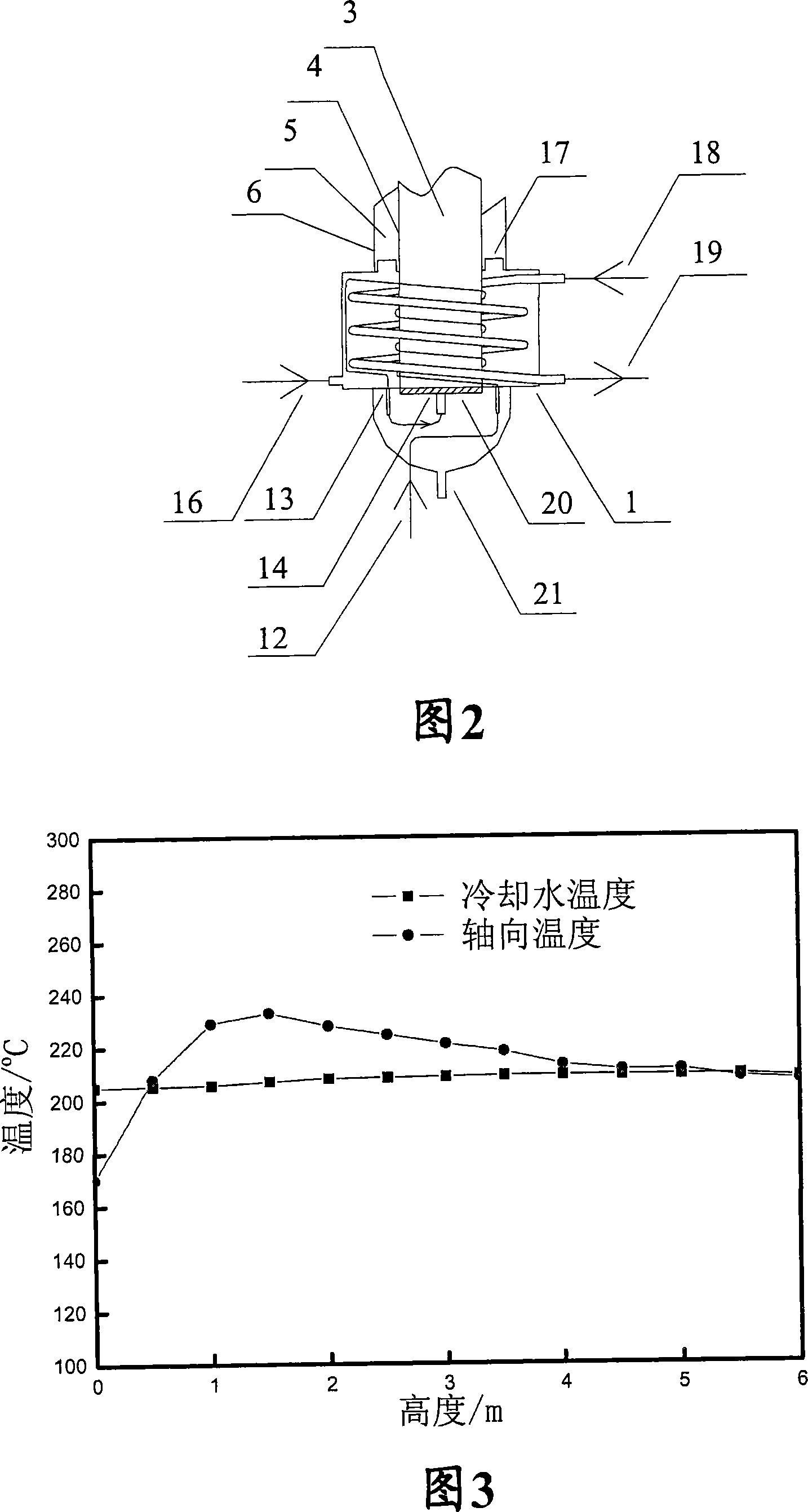
[0042] Embodiment 1: As shown in Figure 1 and Figure 2, it is a single-tube fixed-bed reaction system used by the strong exothermic reaction and method of the present invention, and the device adopted in this embodiment can excellently solve the strong exothermic reaction. The problem of excessive heat ensures the effective progress of the reaction and improves the efficiency of the reaction.

[0043] Fresh syngas (or syngas, feed gas, H 2 / CO ratio is 2.0) after compression, it enters the raw material gas pipeline of heater 1, and indirectly heats with the circulating water heated by the flue gas pipeline (inlet 18) in the heater to about 200 °C and then enters into reactor 4 . The control temperature of the circulating water is preferably 205-210°C (according to the reaction temperature of the strong exothermic reaction, the control temperature of the circulating water should be controlled at not more than 210°C), and the synthesis gas in the reactor passes through the Co c...

Embodiment 2

[0056] As shown in FIG. 4 , it is a flow chart of a pilot-scale strongly exothermic reaction using this device and the multi-tube fixed-bed reactor used. The difference from FIG. 1 is that the reactor in this example is implemented by The single-tube reactor of Example 1 becomes a multi-tube reactor, wherein the multi-tube (multiple gas pipelines) are arranged and distributed on the raw material gas distribution plate 20, and the raw gas inlet 14 provided at the bottom of the reactor 4 is connected with the heating. The raw gas pipeline in the device is connected. Compared with the single-tube reactor, the total feed amount of the multi-tube reactor is large, and the total heat release per unit time is large, so the pipeline II is used to force the circulation of the water through the high-pressure circulating pump, so that the water can be quickly circulated with the reactor. Indirect heat exchange. The water temperature change during the cycle is only 3°C, which ensures tha...


PUM


Abstract

The present invention provides a method that processing a strong exothermic reaction by utilizing the thermostatic heat exchange device; the thermostatic heat exchange device comprises a reactor and a heater arranged at the bottom of the reactor, the method is that utilizing the circulating water which is arranged in the thermostatic heat exchange device and passes through the reactor and the transmitted reaction gas runs from below to the top in the same direction, making the strong exothermic reaction processed in the reactor is always kept in the constant temperature range; and the present invention provides a mew thermostatic heat exchange device, depending on the temperature difference of water or the motive power of the pump, making the water cycles outside the reactor, on one hand , effectively shifting out the heat giving out from the reaction; on the other hand, replenishing the heat for the places lacking of the reaction heat, making the reaction happen in the constant temperature range, thereby guaranteeing the effective process of the reaction and increasing the efficiency of reaction. The thermostatic heat exchange device has the advantages of good heat transferring effect and small temperature variation, and is capable of automatically maintaining the target temperature, in addition, is safe and reliable.

Description

technical field [0001] The invention provides a method for using a constant temperature heat exchange device to carry out a strong exothermic reaction, especially a method for using a constant temperature heat exchange device suitable for a strong exothermic reaction to carry out a gas-solid (or other multiphase) strong reaction with a reaction temperature of less than 350°C. The method of exothermic reaction, this method adopts a new type of constant temperature heat exchange circulation device, with the help of circulating water and the reaction gas in the reactor to travel from bottom to top in the same direction, the large amount of heat released by the reaction is effectively removed, and the reaction heat is insufficient. Energy supplementation is carried out locally, so that the reaction occurs within the "constant temperature range", so as to ensure the effective progress of the reaction and improve the efficiency of the reaction. Background technique [0002] The ga...

Claims


Application Information

Patent Timeline
IPC IPC(8): B01J8/02F28D1/047
Inventor 魏伟胜石勇徐建鲍晓军
Owner BC P INC CHINA NAT PETROLEUM CORP
Why Eureka
Try Eureka