
Whole pass sampling tester

A tester and full-bore technology, applied in the direction of wellbore/well components, earthwork drilling and production, etc., can solve the problems of lower test efficiency, failure to obtain full-open drill string switch well pressure, low work efficiency, etc., and achieve expansion Use the operating range, improve the test success rate, and avoid the effect of blocking flow

Inactive Publication Date: 2008-02-20
刘淑娟
View PDF0 Cites 5 Cited by
  • Summary
  • Abstract
  • Description
  • Claims
  • Application Information

AI Technical Summary

Problems solved by technology

One is the lifting and lowering form. Although this tester can be lifted and lowered along with the drill pipe or oil pipe, it cannot provide a large channel, so that other testing tools or instruments cannot pass through its content, which reduces the testing efficiency and also reduces the test efficiency. Multiple on-off well pressures at various locations on the wide open drill string are not available
The other is a tester that can provide a large channel, but this tester cannot complete the sampling operation while opening and closing the well, and has a single function and low work efficiency
The other is the LPR-N test valve. Although it has a large diameter, it is a pressure-controlled type that requires high-purity nitrogen as a pressure source. There are more preparations before the test and the operation is complicated, which not only increases the cost, but also reduces the test. Efficiency; In addition, in some working environments where oil wells cannot be pressurized, this pressure-controlled tester cannot be tested

Method used


Image

  • Whole pass sampling tester
  • Whole pass sampling tester

Examples


Embodiment Construction

[0018] The present invention will be described in further detail below in conjunction with the accompanying drawings.

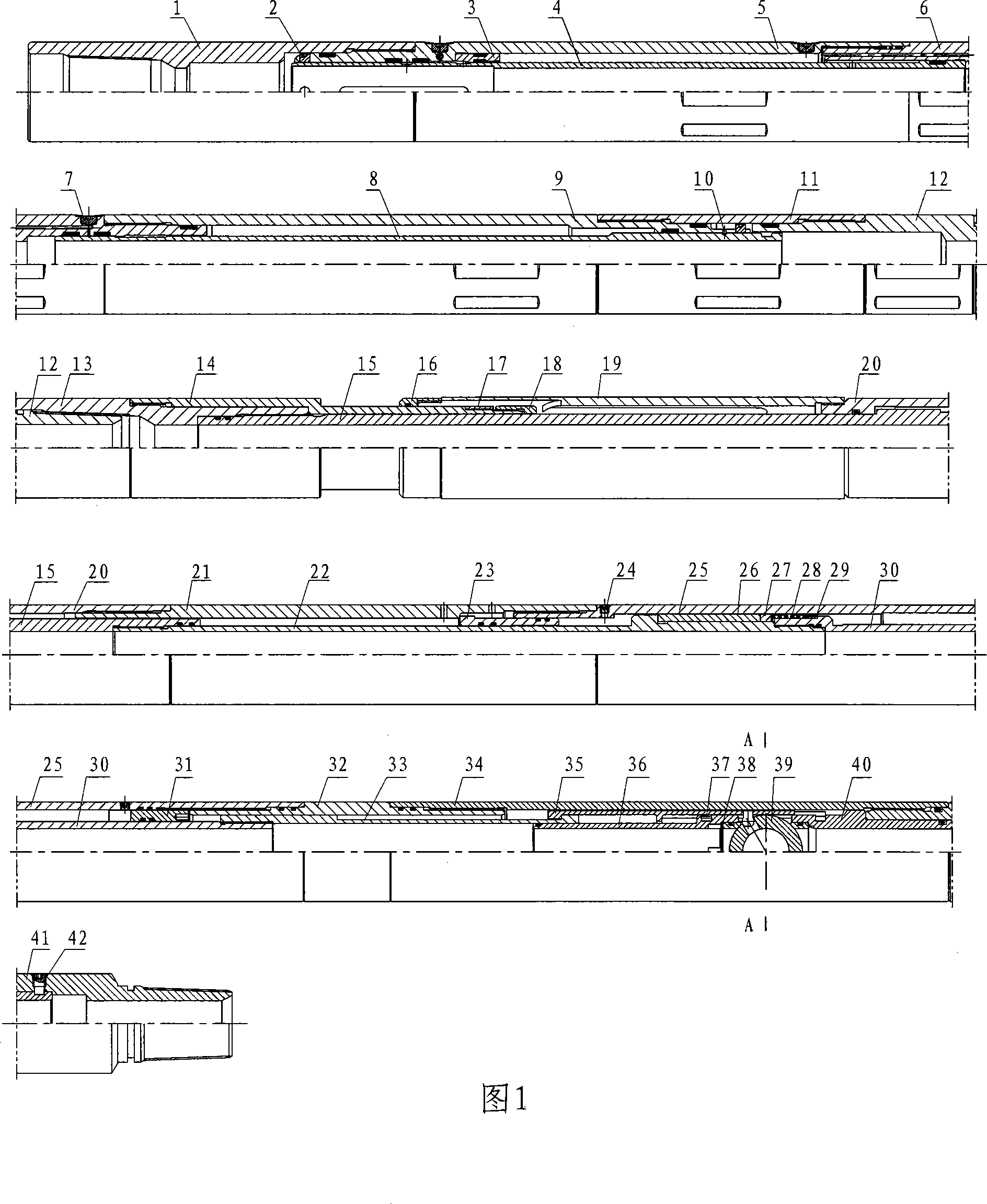
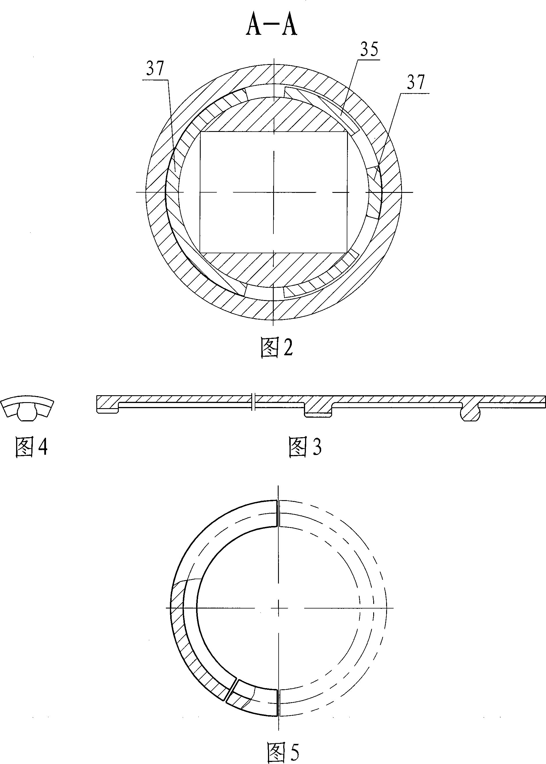
[0019] As shown in Figures 1 to 5, the present invention includes a sampling mechanism, a transposition mechanism, a time-delay mechanism and a ball valve mechanism. The ball valve mechanism is connected to the lower end of the spindle, and the sampling mechanism, transposition mechanism, The mechanism and the time-delay mechanism are connected in sequence, and the mandrel can reciprocate up and down in each mechanism to drive the switch of the ball valve mechanism.

[0020] The delay mechanism is composed of an upper connecting outer cylinder 21, an upper spindle 22, a compensating piston 23, a delay outer cylinder 25, a delay valve 26, a lower spindle 30 and a sealing retaining ring 31. The outer sleeve of the upper and lower spindles 22, 30 of the delay mechanism is provided with a delay outer cylinder 25, one end of which is threadedly connected with the ...


PUM


Abstract

The invention relates to a testing and sampling tool used in well of the oilfield, specifically speaking, an all-size sampling tester which comprises a sampling mechanism, an inversion mechanism, a time-delay mechanism and a ball valve mechanism. The ball valve mechanism is connected with the lower end of a mandrel; the sampling mechanism, the inversion mechanism and the time-delay mechanism are sequentially from top to bottom sleeved at the outer side of the mandrel, the mechanisms are all sequentially connected with each other, the mandrel can move up and down in each mechanism to actuate the switch of the ball valve mechanism. The invention can realize the operation and control on the switch and sampling of the ball valve of the downhole tool under the actuation of the up-down movement of a drill stem or an oil tube. the operation is convenient and the actuation is flexible and reliable; the invention adopts the large-size, large-flow and all-size design and can resist high pressure, which can effectively avoid the choked flow, enlarges the operation scope of the tool, considerably improves the utilization ratio of the tool and the success rate of the test; the ball valve can be repeatedly opened or closed by raising or lowering the drill stem or the oil tube, and thus a plurality of open flow periods and shut-in pressure survey periods can be obtained.

Description

technical field [0001] The invention relates to a testing and sampling tool in the well of an oil field, in particular to a full-bore sampling tester. Background technique [0002] At present, there are three types of testers commonly used in oil fields. One is the lifting and lowering form. Although this tester can be lifted and lowered along with the drill pipe or oil pipe, it cannot provide a large channel, so that other testing tools or instruments cannot pass through its content, which reduces the testing efficiency and also reduces the test efficiency. Multiple on-off well pressures at various locations on the wide open drill string are not available. The other is a tester that can provide a large channel, but this tester cannot complete the sampling operation while opening and closing the well, and has a single function and low work efficiency. The other is the LPR-N test valve. Although it has a large diameter, it is a pressure-controlled type that requires high-pu...

Claims


Application Information

Patent Timeline
Patent Type & Authority Applications(China)
IPC IPC(8): E21B49/08
Inventor 刘淑娟许苏明
Owner 刘淑娟
Learn More