Electronic type transformer high voltage side redundant backup circuit and failure detection method

An electronic transformer, redundant backup technology, applied in the direction of voltage/current isolation, fault location, etc., can solve the problems of poor flexibility, difficult maintenance and replacement, short service life of transformers, etc., to enhance reliability and improve reliability. The effect of convenient performance, maintenance and repair of equipment

Inactive Publication Date: 2008-02-20
BEIHANG UNIV
View PDF0 Cites 8 Cited by
  • Summary
  • Abstract
  • Description
  • Claims
  • Application Information

AI Technical Summary

Problems solved by technology

Since the high-voltage side circuit has been working in a harsh electromagnetic interference environment for a long time, once a fault occurs, the entire electronic transformer will not work normally, and it is difficult to repair and replace it under live conditions. Therefore, the reliability design of the high-voltage side circuit It is the key link to ensure the performance of electronic transformers
[0004] In the design of the high-voltage side circuit of the existing electronic transformer, the method of using conventional integrated circuit design is generally adopted, such as: using multi-channel gating and high-precision analog-to-digital conversion devices to realize time-division multiplexing of multiple signals, Then it is transmitted to the low-voltage side. In this way, the high-voltage side circuit is simple, but the function is single, and the flexibility is poor; there is also a realization method using single-chip microcomputer technology in the design of the high-voltage side circuit. Complicated functions, with the characteristics of flexible setting of data transmission mode between high / low voltage side and strong versatility
However, whether it is implemented by integrated circuits or single-chip microcomputers, there are defects such as short service life of transformers and poor system reliability.

Method used


Image

  • Electronic type transformer high voltage side redundant backup circuit and failure detection method
  • Electronic type transformer high voltage side redundant backup circuit and failure detection method
  • Electronic type transformer high voltage side redundant backup circuit and failure detection method

Examples


Embodiment Construction
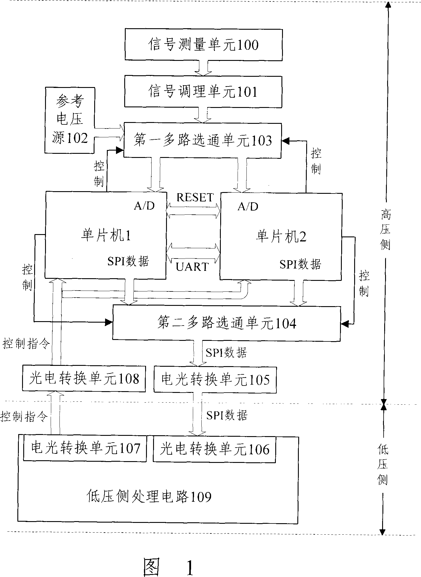
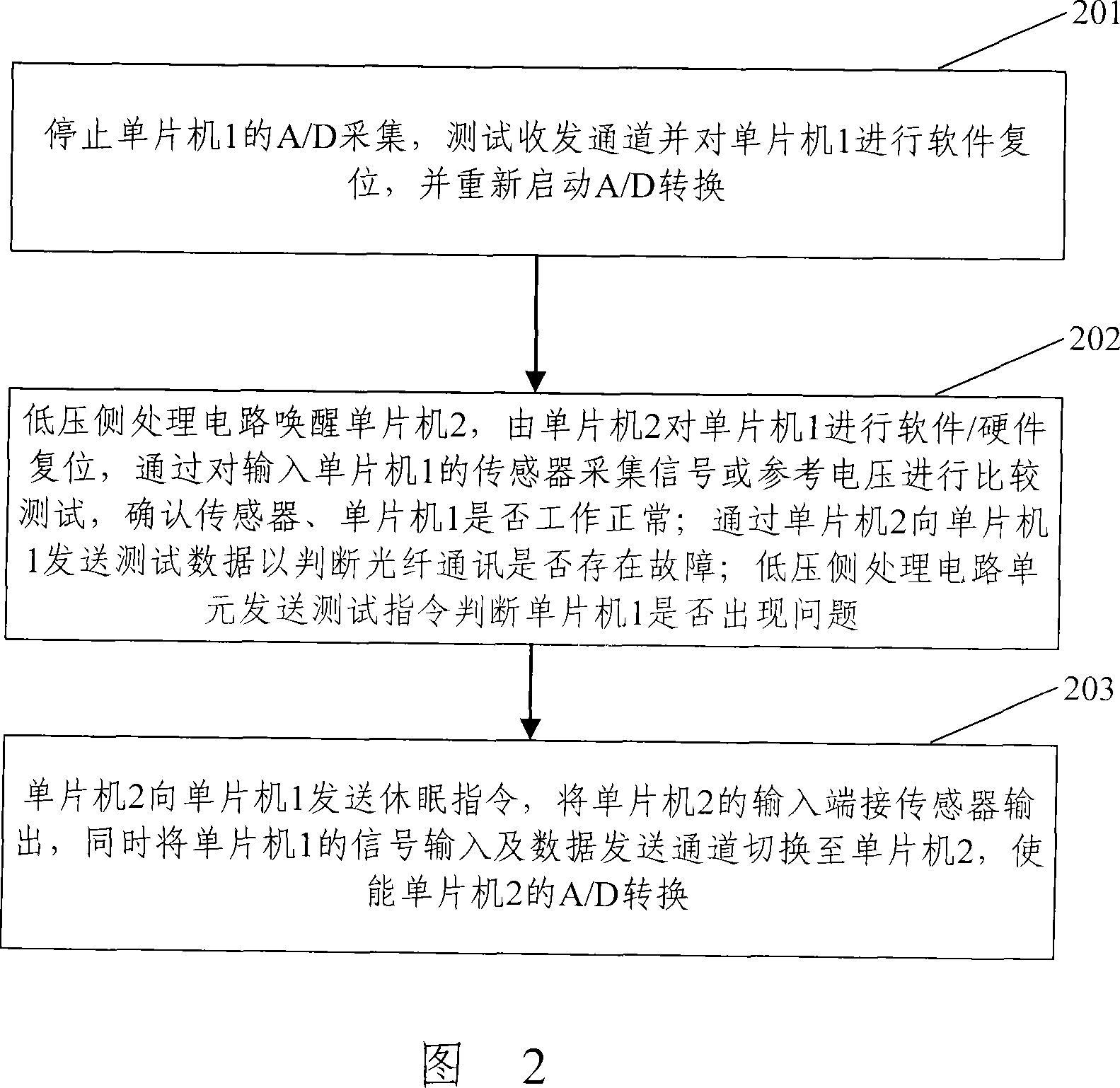
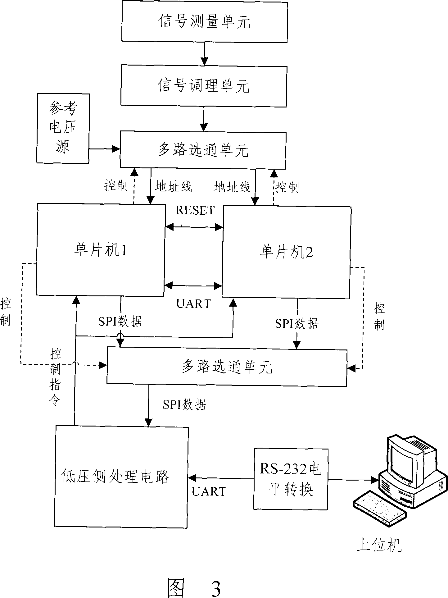
[0026] The core idea of ​​the present invention is: by adding a single-chip microcomputer connected in parallel with the original single-chip microcomputer in the high-voltage side circuit of the electronic transformer, and adding the first multi-channel gating unit and the second multi-channel gating unit at the same time, one of the The single-chip microcomputer is set as the main one, that is, it is in the normal working state, and performs all the functions of the high-voltage side circuit, and the other single-chip microcomputer is set as the backup, that is, it remains dormant; assuming that the original single-chip microcomputer is set as the main one, and the newly added single-chip microcomputer is the backup, and the high-voltage side of the transformer is executed. At the same time as the basic functions of the circuit, when the low-voltage side processing circuit judges that the high-voltage side circuit may be faulty, it will wake up the standby microcontroller on t...


PUM


Abstract

The utility model discloses a redundancy backup circuit at the high-voltage side of electronic transducer , which is characterized in that: the transducer high-voltage side circuit is added with a standby controller connected in parallel with a main controller and a corresponding multi-path gating circuit. When the transducer is in operation, the stand-by controller hibernates, and main controller completes all the functions of high-voltage side circuit. If the low-voltage side circuit judges that the high-voltage side circuit has failure possibility, the stand-by controller arranged on the high-voltage side is awakened. The stand-by controller sends a reset command to the main controller and conduct diagnostic tests over the high-voltage side circuits. If the main controller confirms the presence of faults, the current work of the main controller is switched to the stand-by controller to maintain the normal work of the transducer and overcome the transducer failure as a result of the main controller failure in high-voltage side circuit, thus improving the reliability of the transformer . The utility model also discloses a fault detection method based on the circuit for the provision of fault location information for the overhaul of transducer equipment, which facilitates the online maintenance of the equipment.

Description

technical field [0001] The invention relates to the transformer technology in the technical field of power system automation, in particular to a backup circuit and a fault detection method of an electronic transformer. Background technique [0002] The power transformer is one of the important electrical equipment in the power system. It plays a very important role in the accurate measurement of current / voltage, power metering, relay protection, system monitoring and system analysis in the power system. At present, the traditional electromagnetic current / voltage transformer is still widely used in the power system. With the continuous development of the power system and the continuous improvement of the grid voltage level, the insulation problems and magnetic saturation problems of the traditional electromagnetic current / voltage transformer, Inherent defects such as small dynamic range have become increasingly prominent, so electronic transformer technology has been proposed...

Claims


Application Information

Patent Timeline
Patent Type & Authority Applications(China)
IPC IPC(8): G01R15/18G01R31/08
Inventor 钱政谭宁王丽娜
Owner BEIHANG UNIV
Why Eureka
Try Eureka