LED matrix screen parameter calibration system and method

A technology of parameter correction and dot matrix screen, which is applied in the direction of instruments, electrical components, static indicators, etc., can solve the problems of the microprocessor's point correction processing work, high cost, and address mismatch.

Inactive Publication Date: 2008-02-20
杭州芯翼科技有限公司
View PDF1 Cites 32 Cited by
  • Summary
  • Abstract
  • Description
  • Claims
  • Application Information

AI Technical Summary

Problems solved by technology

[0003] The biggest difficulty encountered in the design of LED dot matrix screen is the consistency problem: on the one hand, due to the deviation of the manufacturing process, the LED dot matrix in the large-size LED screen has different display brightness under the same driving current; on the other hand, On the one hand, due to the differences in the driving circuit components of each part of the LED dot matrix, the deviation of the actual driving current is caused, which leads to uneven brightness of the LED dot matrix screen and affects the display quality of the picture.
The disadvantage of this dot correction method applied to large LED dot matrix screens is that the dot correction parameters written in memory in advance must correspond to the address of each cascaded LED dot matrix block in the system. For cascaded LED dot matrix blocks, all the calibration parameters in the memory must be erased and rewritten, resulting in poor system flexibility; moreover, this system does not have automatic error correction capabilities, and it is easy to appear in the actual large-screen assembly process. The assembly address of a certain LED dot matrix does not correspond to the address of the calibration parameters in the memory

Method used


Image

  • LED matrix screen parameter calibration system and method
  • LED matrix screen parameter calibration system and method
  • LED matrix screen parameter calibration system and method

Examples


Embodiment Construction

[0065] Embodiments of the present invention will be described in detail below in conjunction with the accompanying drawings.

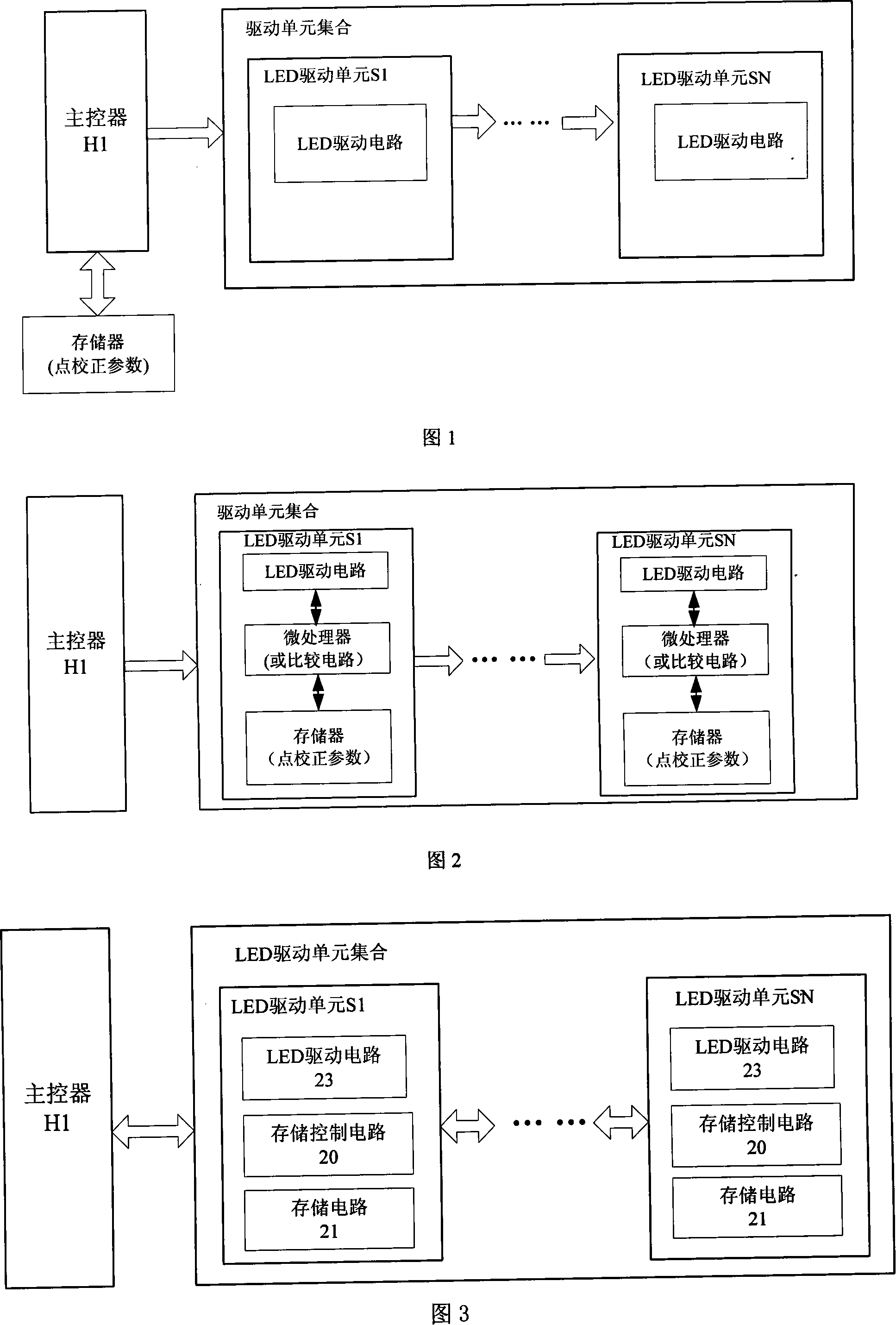
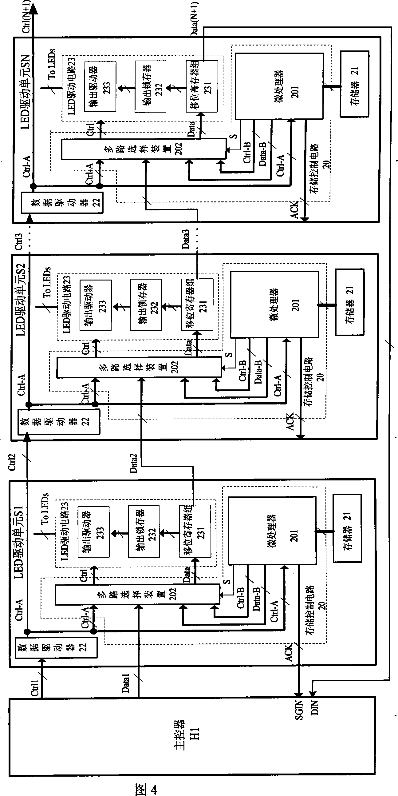
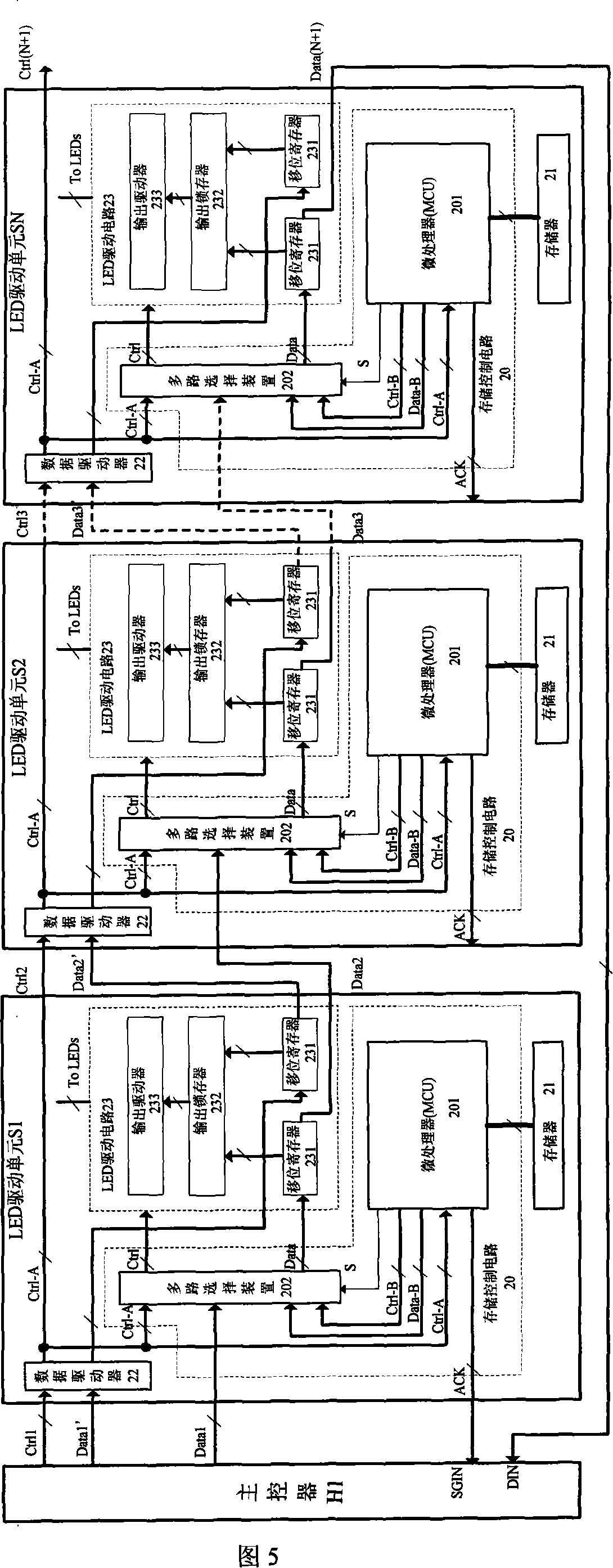
[0066] Fig. 3 is a structural schematic diagram of the LED dot matrix screen parameter calibration system, the LED dot matrix screen parameter calibration system includes a master controller (H1) and several cascaded LED drive units (S1-SN), the LED drive unit ( S1-SN) includes a storage circuit (21), a storage control circuit (20) and an LED drive circuit (23), wherein the storage circuit (21) stores the point correction parameters of the LED drive unit at the current stage.

[0067] Wherein, the storage circuit (21) is a non-volatile storage circuit, and its characteristic is that it does not disappear when power is off and can be rewritable. The point correction parameters are written by the manufacturer before the LED unit board leaves the factory. It can be erased and rewritten by the user.

[0068] Wherein, when the LED dot matrix screen paramet...


PUM


Abstract

The utility model discloses a parameter correction system and method of LED matrix screen, comprising a main controller and a plurality of LED driving units, which is characterized in that the LED driving unit comprises a storage circuit, a storage control circuit and a LED driving circuit, wherein the storage circuit storages the point correction parameter of the LED matrix of the current-level LED driving unit. When the parameter correction system of the LED matrix screen reads the correction parameters, the main controller controls the LED driving unit and a communication channel is established between the main controller and the LED driving unit, the point correction parameters stored in the storage circuit of the LED driving unit are read to the main controller by the main controller and the storage control circuit of respective-level LED driving unit through the communication channel, the main controller finishes the operation and contrast of the point correction parameters, and transfers the actual display values to the LED driving circuit of the LED driving unit.

Description

technical field [0001] The invention relates to a system and method for calibrating parameters of LED dot matrix screens, in particular to a system and method for calibrating parameters of LED dot matrix screens with unitized design. Background technique [0002] With the improvement of LED (light-emitting diode) production process level and the improvement of luminous efficiency, especially the emergence of red, green and blue high-brightness LED devices, the spectrum of LED devices covers the range of natural light, and the use of LEDs to manufacture dot matrix screens has become Become an important field of LED application. [0003] The biggest difficulty encountered in the design of LED dot matrix screen is the consistency problem: on the one hand, due to the deviation of the manufacturing process, the LED dot matrix in the large-size LED screen has different display brightness under the same driving current; on the other hand, On the one hand, due to the differences in...

Claims


Application Information

Patent Timeline
IPC IPC(8): G09G3/32G09G5/36G09G5/39H05B33/08H05B33/14H05B37/02H05B44/00
Inventor 郑尊标周忠良陈向东
Owner 杭州芯翼科技有限公司
Why Eureka
Try Eureka