Energy storage system for magnetic floating flywheel

A technology of flywheel energy storage and magnetic levitation, which is applied in the direction of flywheel, mechanical energy control, electrical components, etc., can solve the problems of high manufacturing cost, small power storage, and small energy storage of "flywheel", and achieve the effect of low manufacturing cost and small self-weight

Inactive Publication Date: 2008-02-20
严密 +1
View PDF2 Cites 20 Cited by
  • Summary
  • Abstract
  • Description
  • Claims
  • Application Information

AI Technical Summary

Problems solved by technology

[0014] Because the "flywheel" of the prior art contains many permanent magnet material parts; according to the above-mentioned known one, under the condition of equivalent quality and rotational speed, the rotational angular velocity of the "flywheel" moment of inertia is relatively small because of the low resistance of the permanent magnet material. Due to the influence of tensile strength and large specific gravity, the quality of the "flywheel" cannot be concentrated to the steel parts with higher tensile strength and larger radius of rotation, and the radius of rotation of the moment of inertia is smaller", then, according to the above-mentioned known 2, its " "Flywheel" has less energy storage
[0015] Therefore, according to the above-mentioned known knowledge three, the prior art has the disadvantage of small storage capacity
[0016] 3. The "magnetic bearing" of the prior art is only limited to two groups of "permanent magnetic material part pairs" (that is, a pair of permanent magnetic material parts that use magnetic repulsion to achieve the task of magnetic levitation motion support), axial and radial movement The support is "full magnetic suspension bearing" with magnetic suspension support;
[0023] Therefore, there is the shortcoming that manufacturing cost is high in the prior art
[0024] 4. In the prior art, there is no device specially designed to prevent the "pair of permanent magnetic material parts" of its "magnetic bearing" from colliding with itself
[0035] When the "permanent magnet rotating electrical machine device" of the prior art is in operation, the surface area of ​​its rotor permanent magnet material parts participating in the excitation is fixed; The value corresponds to the real-time rotational angular velocity of its rotor perman

Method used


Image

  • Energy storage system for magnetic floating flywheel
  • Energy storage system for magnetic floating flywheel
  • Energy storage system for magnetic floating flywheel

Examples


Embodiment Construction

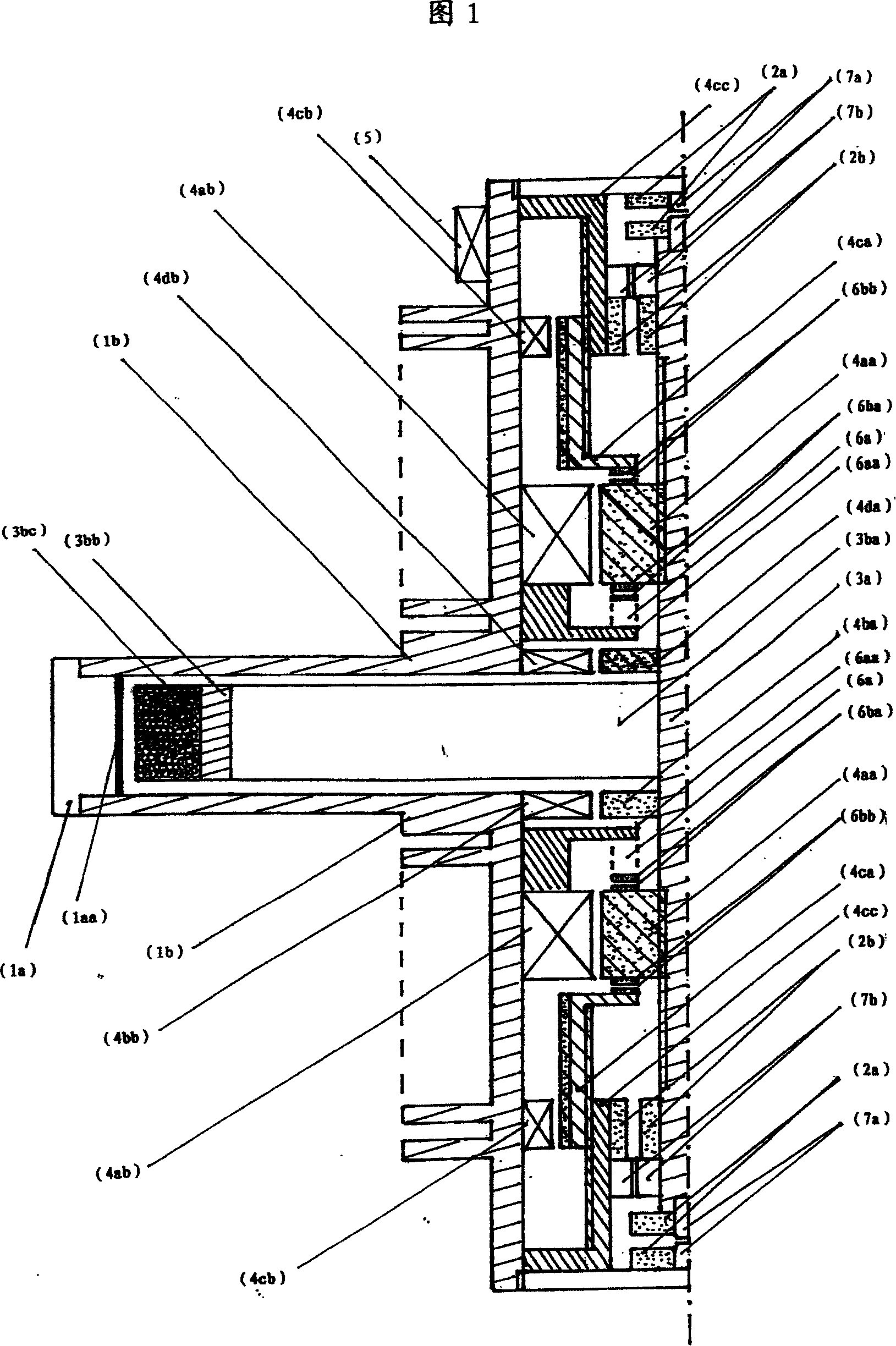
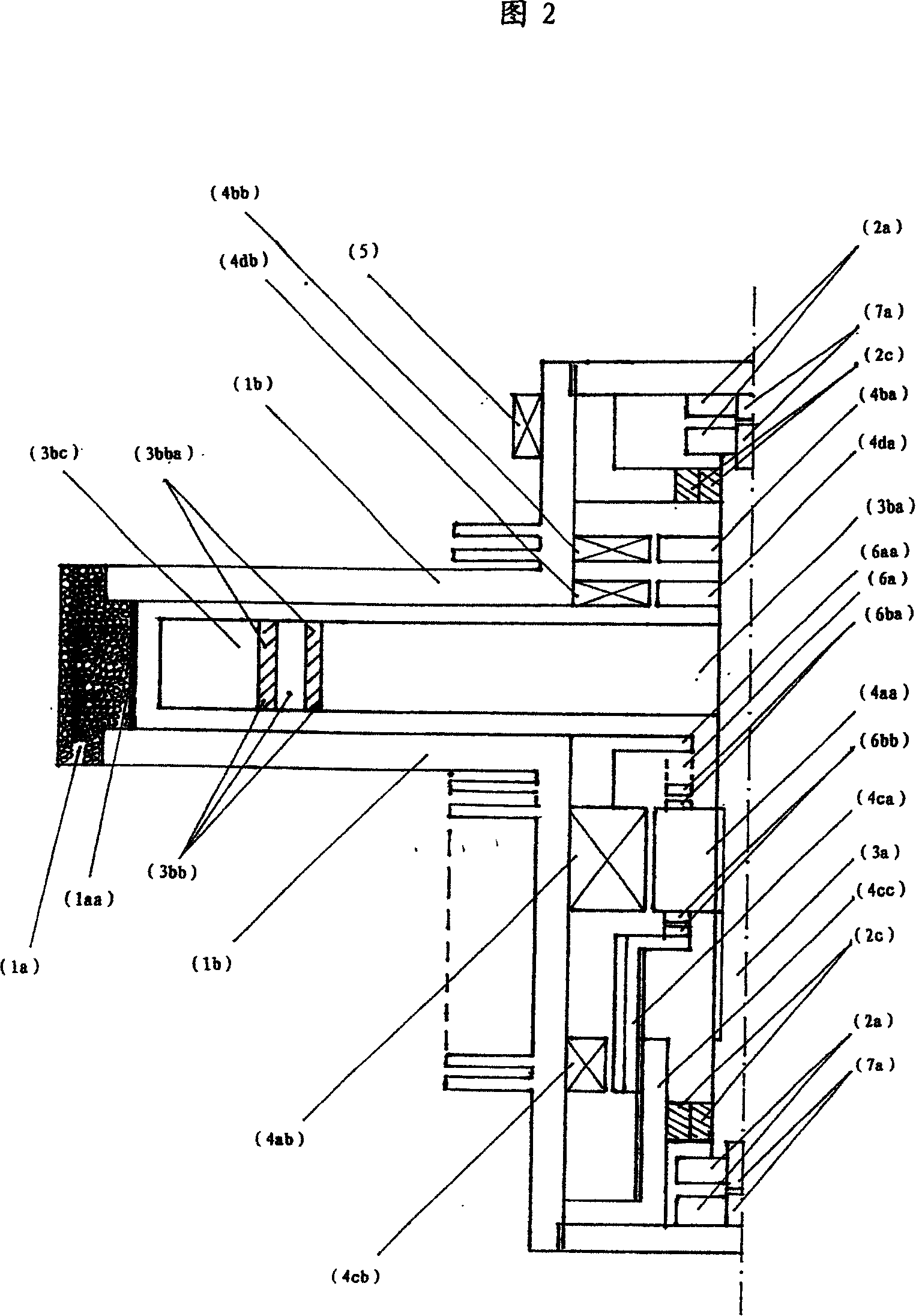
[0100] In the two embodiments of the present invention, the structure of the magnetic levitation flywheel energy storage system is shown in Figure 1 and 2 respectively; Rotating electrical machine device"...consists of.

[0101] The axial part of the "high-vacuum sealed casing" of the magnetic levitation flywheel energy storage system shown in Figures 1 and 2 is formed by joining the "part to prevent flywheel debris from escaping" (1a) and the "radiation part" (1b).

[0102] The radially inner edge of the "preventing the escape of flywheel broken objects" is facing the radially outer edge of the "flywheel" and "roulette" "because when the "flywheel" rotates at high speed, the "flywheel" and "roulette" are used for The steel part that provides the moment of inertia has the largest kinetic energy, and its broken objects are the most destructive, and the broken objects are scattered in the direction of centrifugal force, and its axial length is only slightly larger than the axial...


PUM


Abstract

The utility model discloses a magnetic levitation flywheel energy accumulation system, which has the advantages of small deadweight, large electricity storage, low manufacturing cost, mobile usage, free adjustment of the real-time discharge quantity value to the outside, and quick charge or large real-time discharge; wherein, the axial component of ''the high-vacuum enclosed housing'' is made of materials of low specific gravity. No permanent magnetic material components are positioned on the ''Flywheel'' and the ''Wheel Disk'' is divided into three rings. Four ''Permanent Magnetic Rotating Motor Devices'' are arranged. The ''Magnet bearing'' is ''all magnetic levitation bearing'' or ''semimagnetic levitation bearing''. The utility model is also provided with a device to guarantee the reliability of the mobile usage of the ''Magnet Bearing''.

Description

(1) Technical field [0001] The invention relates to the technical field of electric storage devices. (2) Background technology [0002] The magnetic levitation flywheel energy storage system is a kind of physical battery. [0003] The magnetic levitation flywheel energy storage system in this article refers specifically to one: it consists of "high vacuum sealed shell", "magnetic bearing", "flywheel", and "permanent magnet rotating motor device" "The "permanent magnet rotating motor device" is all The rotor adopts permanent magnets and the stator adopts electric excitation "permanent magnet rotating electrical machine device". It consists of an energy storage system that stores mechanical energy instead of storing electrical energy; for example: "US Patent No. US-5124605" or "China The energy storage system described in Patent No. 01126564.7". [0004] The maglev flywheel energy storage system uses its "permanent magnet rotating motor device" to allow its "flywheel" to exc...

Claims


Application Information

Patent Timeline
IPC IPC(8): H02K7/02H02K7/09F16F15/30
CPCY02E60/16
Inventor 唐荫溥
Owner 严密
Why Eureka
Try Eureka