
Programmable gain amplifier

A programming gain and amplifier technology, applied in the direction of analog-to-digital converters, etc., can solve the problems of not being able to save the capacitor CF area, and cannot provide a variety of control mechanisms, so as to achieve the effect of saving the capacitor area and reducing the area

Inactive Publication Date: 2008-02-27
SUNPLUS TECH CO LTD
View PDF2 Cites 12 Cited by
  • Summary
  • Abstract
  • Description
  • Claims
  • Application Information

AI Technical Summary

Problems solved by technology

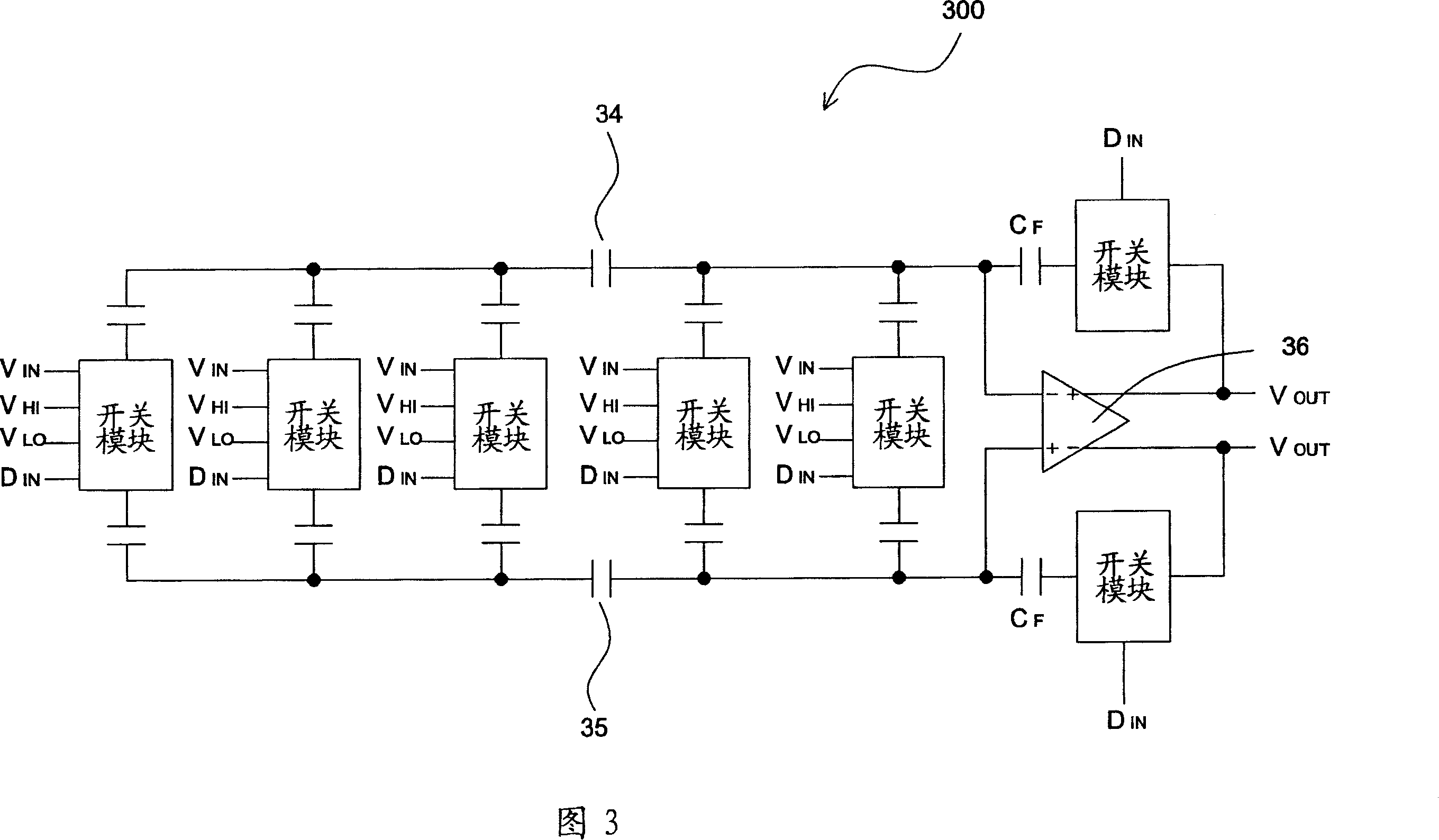
[0006] However, in the aforementioned programmable gain amplifier 300, only the capacitor C F Used as a feedback capacitor
In other words, the programmable gain amplifier 300 can only achieve the purpose of gain control by adjusting the equivalent capacitance value of the sampling capacitor, which not only cannot provide a variety of control mechanisms, but also cannot save the capacitor C F the area of

Method used


Image

  • Programmable gain amplifier
  • Programmable gain amplifier
  • Programmable gain amplifier

Examples


Embodiment Construction

[0034] The programmable gain amplifier of the present invention will be described in detail below with reference to the figures.

[0035] FIG. 4A is a schematic diagram of a first embodiment of a programmable gain amplifier 400 of the present invention. In this embodiment, the programmable gain amplifier 400 is a 4-bit programmable gain amplifier. The programmable gain amplifier 400 includes an operational amplifier 110, two groups (N+1 group) of adjustment capacitor modules 402, 404, two groups (N+1 group) of switch modules 406, 408, and a feedback switch S F , one (N) attenuation capacitor C SC A feedback capacitor C F , and a control module 430 . Wherein N is a positive integer greater than 0, and N is 1 in this embodiment.

[0036] As shown in FIG. 4A , the first group of adjustment capacitor modules 402 includes capacitors C1 and C2 with first terminals connected to each other; the second group of adjustment capacitor modules 404 includes capacitors C3 and C4 with fir...


PUM


Abstract

A programmable gain amplifier comprises: an operational amplifier, N (N>0) attenuation capacitances, N+1 group of control capacitance modules, multiple change-over switches, a change-over control module and a feedback switch. Each group of control capacitance module has at least one control capacitance. Each change-over switch is controlled by the change-over control module, the common ends of the switches are respectively connected with the second end of the control capacitances, the capacitances, by said connection, are connected with an input signal, a reference voltage, or the output end of the operational amplifier. The feedback amplifier connects between the output end and No.1 input end of the operational amplifier, it is getting-through at No.1 phase period, and cutting-off at other period. At No.2 phase period, the control capacitance can be connected, controlled by the change-over switch, the output end of the operational amplifier to be used as feedback capacitance.

Description

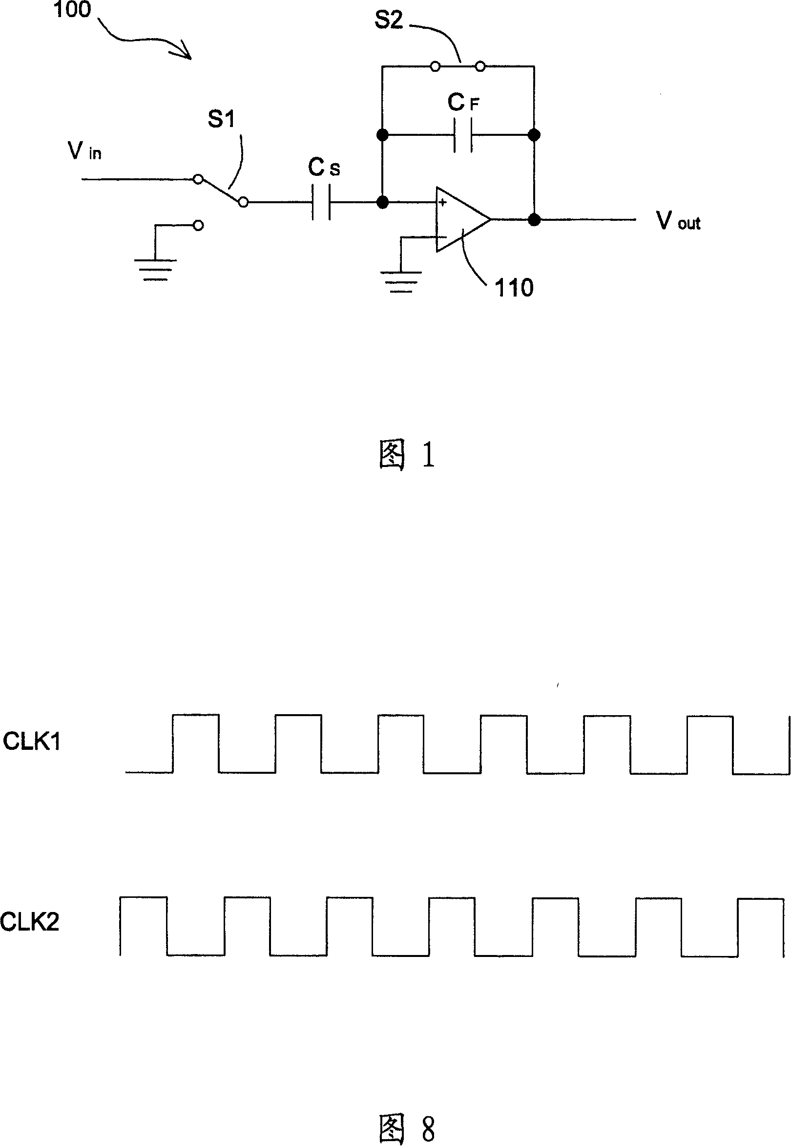
technical field [0001] The invention provides a gain amplifier, especially a programmable gain amplifier with an attenuation capacitor and a sampling capacitor that can be switched to a feedback capacitor. Background technique [0002] FIG. 1 is a schematic diagram of an amplifier 100 in the form of a conventional switched capacitor. As shown in Figure 1, the amplifier 100 includes a sampling capacitor Cs, a feedback capacitor C F , two switches S1 , S2 , and an operational amplifier 110 . The operation of the amplifier 100 is as follows: in a first phase (sampling phase), the switch S1 is connected to the input signal Vin, and the switch S2 is turned on. Therefore, the sampling capacitor Cs charges and samples the input signal Vin during the first phase. In a second phase (amplification phase), the switch S1 will be connected to the ground potential, and the switch S1 will be turned on to form an open circuit. At this time, the charge stored in the sampling capacitor Cs ...

Claims


Application Information

Patent Timeline
Patent Type & Authority Applications(China)
IPC IPC(8): H03M1/18
Inventor 欧阳铭林盟智
Owner SUNPLUS TECH CO LTD
Learn More