Microelectron mechanical microwave signal phase detector and method for preparing the same

A phase detector, micro-electromechanical technology, applied in the phase angle between voltage and current, generator/motor, piezoelectric/electrostrictive/magnetostrictive devices, etc., can solve the problem of DC power consumption, measurement signal Problems such as small bandwidth and low measurement accuracy can achieve the effect of improving the dynamic range, reducing the influence of inaccurate measurement power, and weakening the requirements

Inactive Publication Date: 2008-03-05
SOUTHEAST UNIV
View PDF0 Cites 59 Cited by
  • Summary
  • Abstract
  • Description
  • Claims
  • Application Information

AI Technical Summary

Problems solved by technology

Traditional microwave signal phase detectors are all based on diode or normal effect tube structure, they all need to consume DC power, and some of them have the following problems: the amplitude of the measureme

Method used


Image

  • Microelectron mechanical microwave signal phase detector and method for preparing the same
  • Microelectron mechanical microwave signal phase detector and method for preparing the same
  • Microelectron mechanical microwave signal phase detector and method for preparing the same

Examples


Example Embodiment

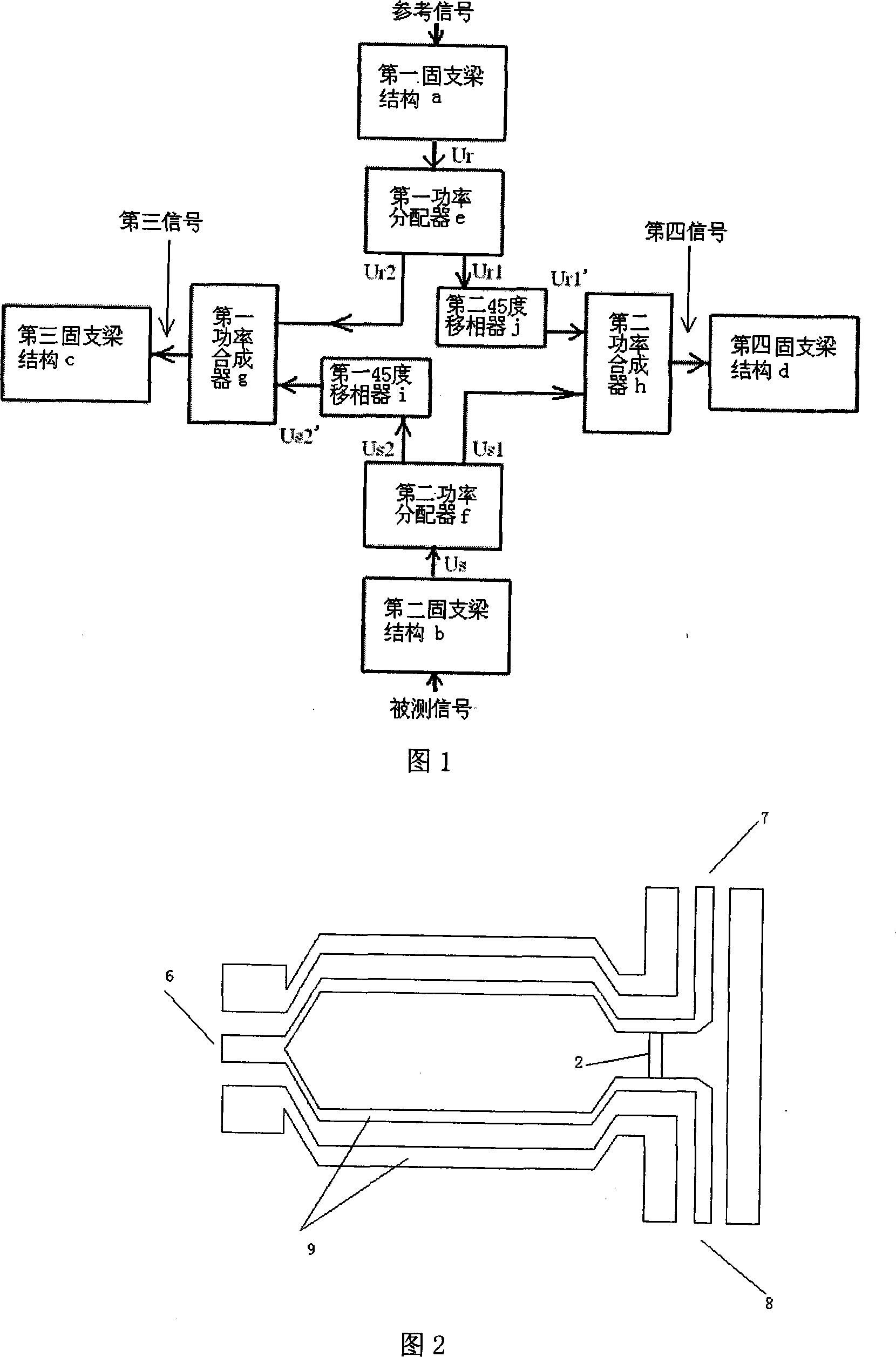
[0042] The microelectromechanical microwave signal phase detector of the present invention takes GaAs substrate as the substrate, and the specific implementation scheme is as follows:

[0043] On the substrate 1 are provided a first fixed beam structure a, a second fixed beam structure b, a third fixed beam structure c, a fourth fixed beam structure d, a first power splitter e, and a second power splitter Device f, first power combiner g, second power combiner h, first 45° phase shifter i, second 45° phase shifter j:

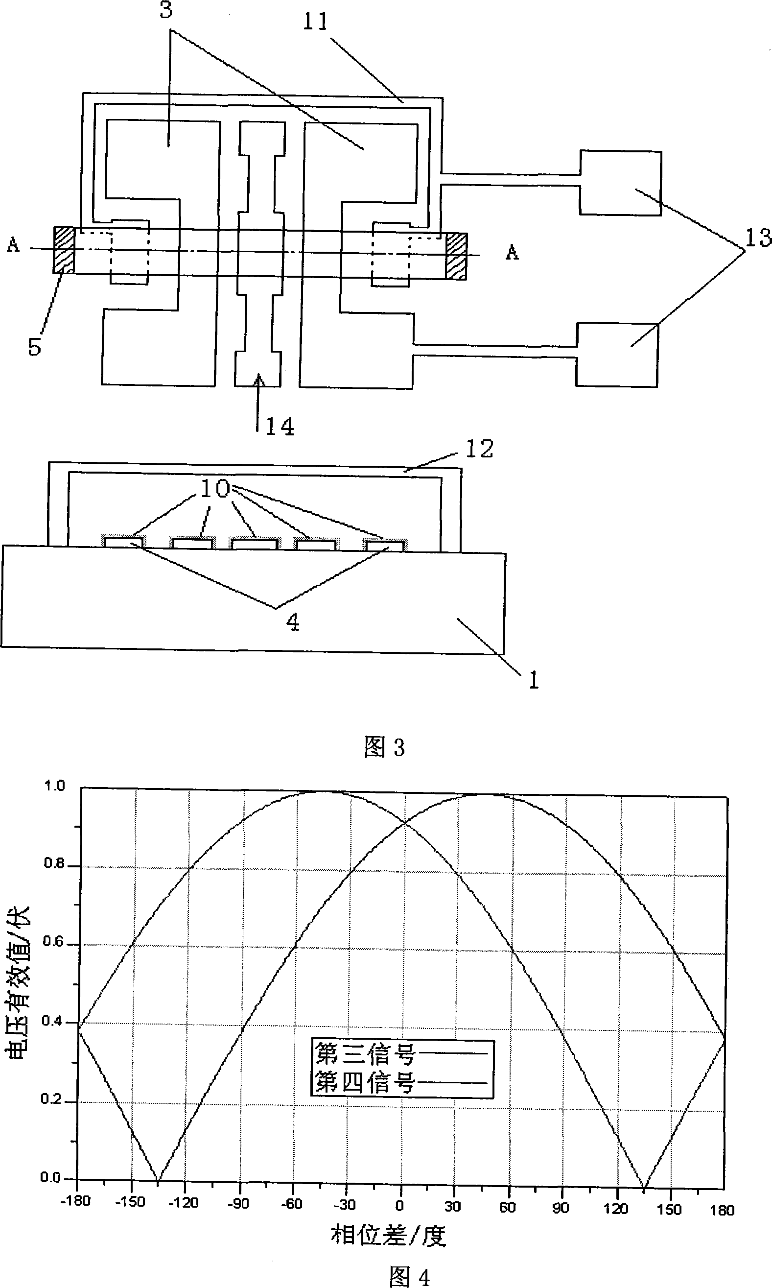
[0044] The first fixed-supported beam structure a, the second fixed-supported beam structure b, the third fixed-supported beam structure c, and the fourth fixed-supported beam structure d use gallium arsenide as the lining 1 and have a CPW in the middle of the substrate 1 The signal line 14 is provided with the ground wire 3 of the CPW on both sides of the signal line 14 of the CPW, and the sensing electrodes 4 are respectively arranged on both sides of the grou...


PUM


Abstract

The method thereof comprises: setting up a first clamped-end beam structure, a second clamped-end beam structure, a third clamped-end beam, a fourth clamped-end beam structure, a first power distributor, a second power distributor, a first power a combiner, a second power combiner, a first 45 deg shifter, and a second 45 deg shifter on the substrate.

Description

technical field [0001] The invention proposes a microwave signal phase detector based on micro-electro-mechanical system (MEMS) technology, which belongs to the technical field of micro-electro-mechanical systems. Background technique [0002] In microwave research, microwave signal phase is an important parameter to characterize microwave signal characteristics, and the measurement of microwave signal phase plays a very important role in microwave wireless application and measurement technology. Traditional microwave signal phase detectors are all based on diode or normal effect tube structure, they all need to consume DC power, and some of them have the following problems: the amplitude of the measurement signal is required to be known and its value is relatively small, and the bandwidth of the measurement signal is relatively small. Small, the measurement accuracy is not high, and the measurable phase is only half a cycle, etc. [0003] In the past 20 years, with the rap...

Claims


Application Information

Patent Timeline
IPC IPC(8): G01R25/00G01R25/02G01R25/04B81B7/02B81C1/00
Inventor 廖小平焦水昌
Owner SOUTHEAST UNIV
Why Eureka
Try Eureka