Disc brake caliper and manufacturing method of disc brake caliper

A disc brake and caliper technology, which is applied to brake components, brake types, axial brakes, etc., can solve the problems of increasing temperature, reducing caliper strength, reducing temperature, etc., to improve surface hardness, good rust prevention and The effect of anti-aging properties

Active Publication Date: 2008-03-05
AKEBONO BRAKE IND CO LTD +1
View PDF4 Cites 4 Cited by
  • Summary
  • Abstract
  • Description
  • Claims
  • Application Information

AI Technical Summary

Problems solved by technology

A caliper that repeatedly raises and lowers temperature si...

Method used


Image

  • Disc brake caliper and manufacturing method of disc brake caliper
  • Disc brake caliper and manufacturing method of disc brake caliper
  • Disc brake caliper and manufacturing method of disc brake caliper

Examples


Embodiment Construction

[0036] Exemplary embodiments of the present invention are described with reference to the drawings.

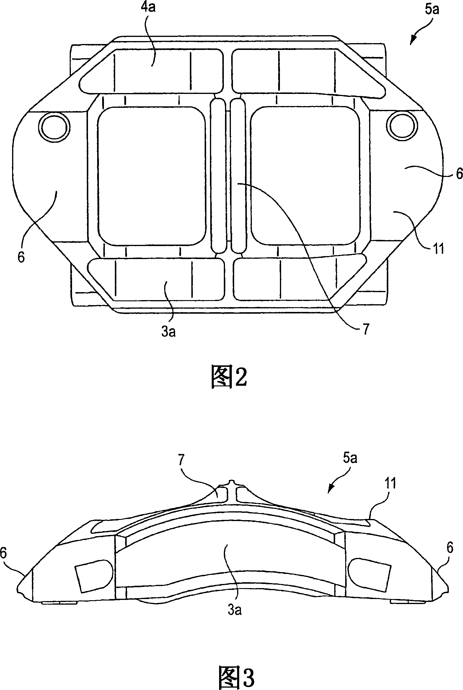
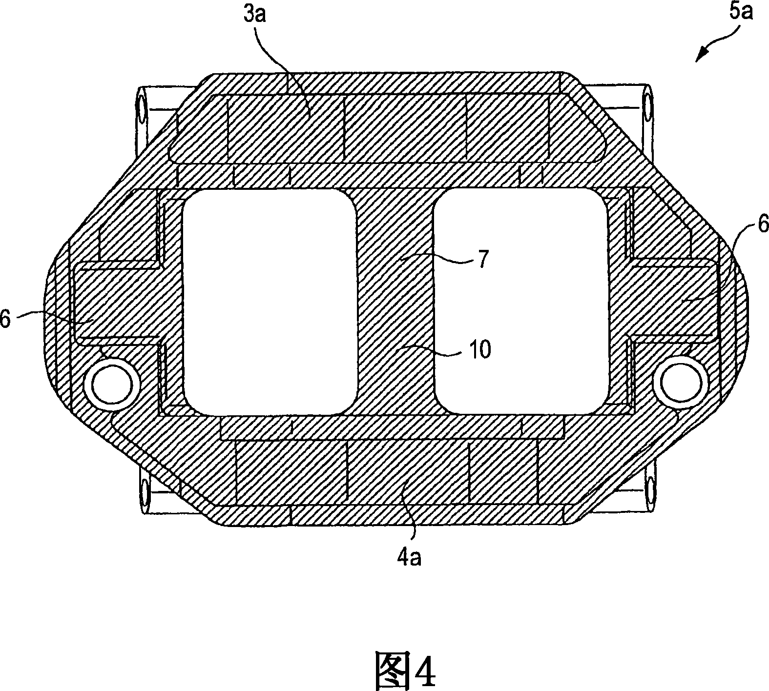
[0037] 2 to 8 show exemplary embodiments of the invention. The disc brake caliper 5a in the embodiment is used in a state where the disc brake caliper 5a is arranged in a bridging state over the periphery of the rotor 2 (refer to FIG. 10 ) rotating together with the wheel. The caliper 5a is integrally formed of an aluminum alloy material, such as A6061 material. The caliper 5a includes an axial direction along the rotor 2 (a vertical direction in FIGS. 2 and 4 , a front-rear direction in FIG. 3 , an oblique up-down direction in FIG. 5 , and an oblique left-right direction in FIG. 6 ). The outer body portion 3a and the inner body portion 4a arranged on both sides, and the surrounding direction for the two body portions 3a and 4a (left-right direction in FIGS. , and in FIG. 6 is an inclined up and down direction) a pair of coupling portions 6, 6 that couple the two end portion...


PUM


Abstract

After chemical nickel plating has been applied onto a rotor-side surface 10 of a caliper 5a made of aluminum alloy and an opposite surface 11 disposed in an opposite side of the rotor-side surface, nickel-tungsten alloy plating is applied onto these both surfaces 10, 11. Then, gold plating is applied onto only the rotor-side surface 10. As a result, a reflectance to incident light on the rotor-side surface 10 is made higher than a reflectance to incident light on the opposite surface 11.

Description

technical field [0001] The present invention relates to a disc brake caliper installed in a disc brake for braking a vehicle such as an automobile, and a method of manufacturing the disc brake caliper. Background technique [0002] In order to brake an automobile, disc brakes are widely used. In braking by a disc brake, a piston presses a pair of pads arranged on both sides in the axial direction of a rotor that rotates with a wheel against both sides of the rotor. As such disc brakes, disc brakes of various structures are known. A stable braking power can be obtained from an opposed-piston disc brake in which pistons are disposed on both sides of a rotor in a state facing each other. Therefore, such opposed-piston disc brakes are increasingly used recently. [0003] FIG. 10 shows an opposed-piston disc brake of the type described in JP-U-05-027364. In an opposed-piston disc brake 1 , a caliper 5 consisting of an outer body 3 and an inner body 4 is provided in a position...

Claims


Application Information

Patent Timeline
IPC IPC(8): F16D55/02
CPCF16D2065/785F16D2055/0016F16D2250/0046F16D65/847F16D55/02
Inventor 根岸利行新堀浩史菅谷政雄市毛孝幸野口哲弥小川铁也
Owner AKEBONO BRAKE IND CO LTD
Why Eureka
Try Eureka