Enzyme mark instrument spectrophotometric detecting optical system, and light diaphragm and optical filter wheel thereof

A spectrophotometry, optical system technology, applied in spectrometry/spectrophotometry/monochromator, optics, nonlinear optics, etc., can solve the problems of small edge energy, space limitation, increase manufacturing cost, etc. Uniformity, reducing the effect of vignetting

Active Publication Date: 2008-03-12
SHENZHEN MINDRAY BIO MEDICAL ELECTRONICS CO LTD
View PDF0 Cites 17 Cited by
  • Summary
  • Abstract
  • Description
  • Claims
  • Application Information

AI Technical Summary

Problems solved by technology

[0007] 1) The scheme of using cold reflectors in the optical path is generally to turn the optical path by 90 degrees, and place the cold reflectors at 45 degrees, which has certain restrictions on space, and the parameters of the cold reflectors need to be adjusted repeatedly according to the energy of each wavelength of the optical path, and the cost Higher and have a greater risk of failure;
[0008] 2) The scheme of adding an attenuator before the filter needs to be matched with the corresponding attenuator, which increases the manufacturing cost;
[0009] 3) The use of energy matching filters will increase the difficulty of the coating process, and the risk of failure of low transmittance filters is greater;
[0010] 4) The solution of the diaphragm with a central hole is uneven in the image plane and the edge energy is small, which cannot ensure that the energy obtained by each fiber splitting is uniform

Method used


Image

  • Enzyme mark instrument spectrophotometric detecting optical system, and light diaphragm and optical filter wheel thereof
  • Enzyme mark instrument spectrophotometric detecting optical system, and light diaphragm and optical filter wheel thereof
  • Enzyme mark instrument spectrophotometric detecting optical system, and light diaphragm and optical filter wheel thereof

Examples


Embodiment Construction

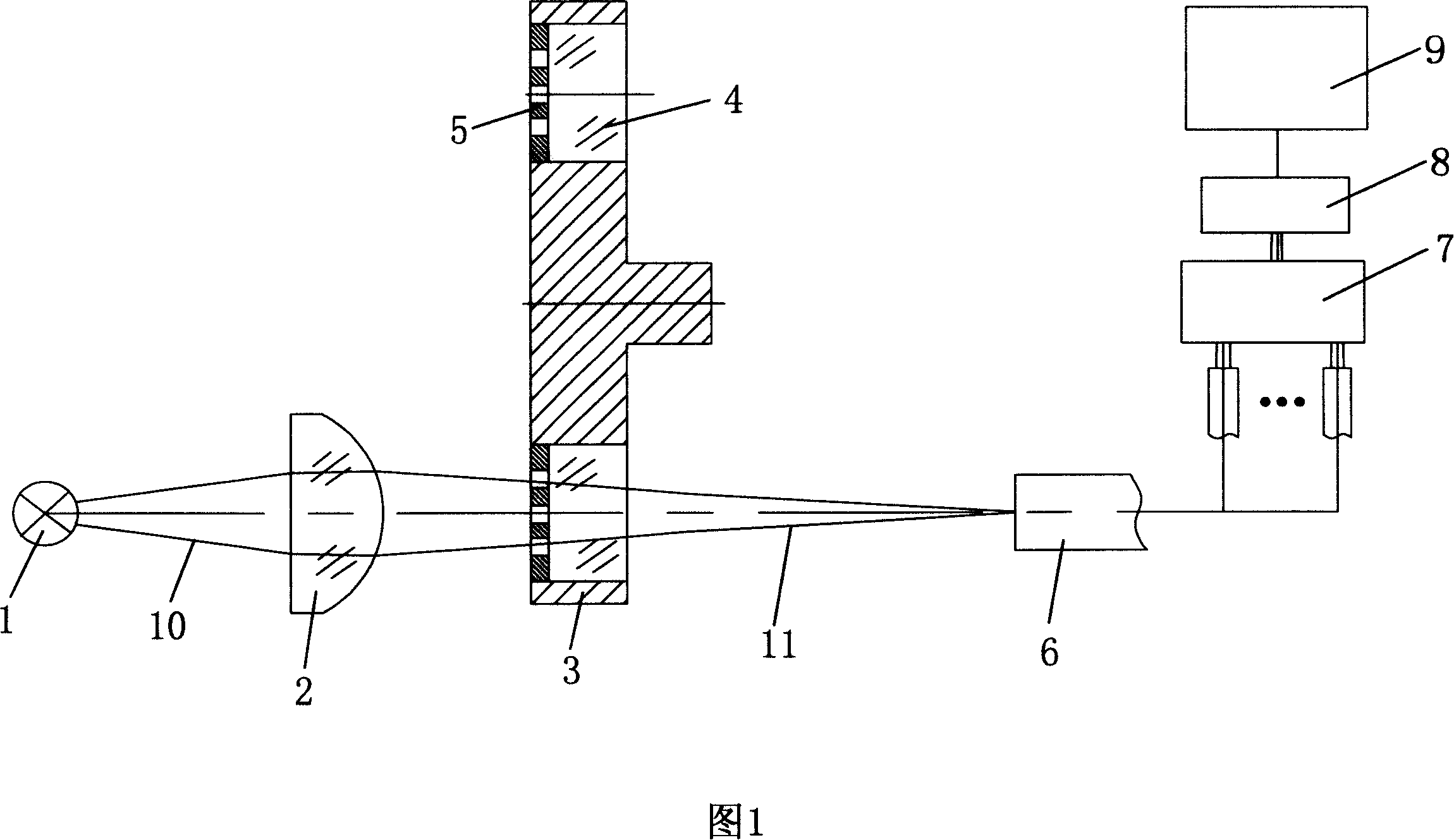
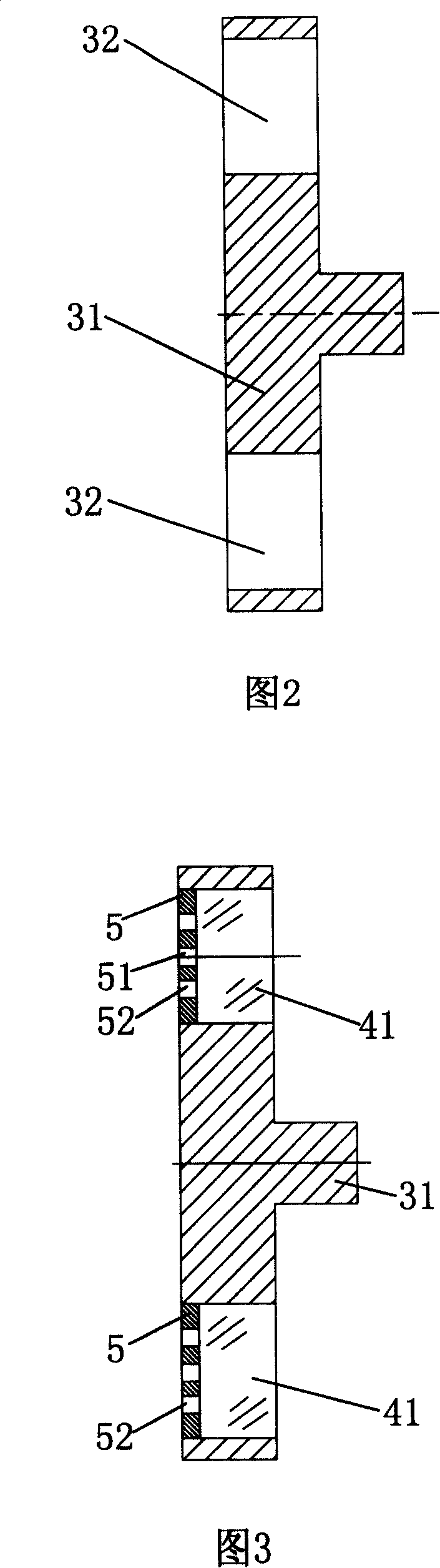
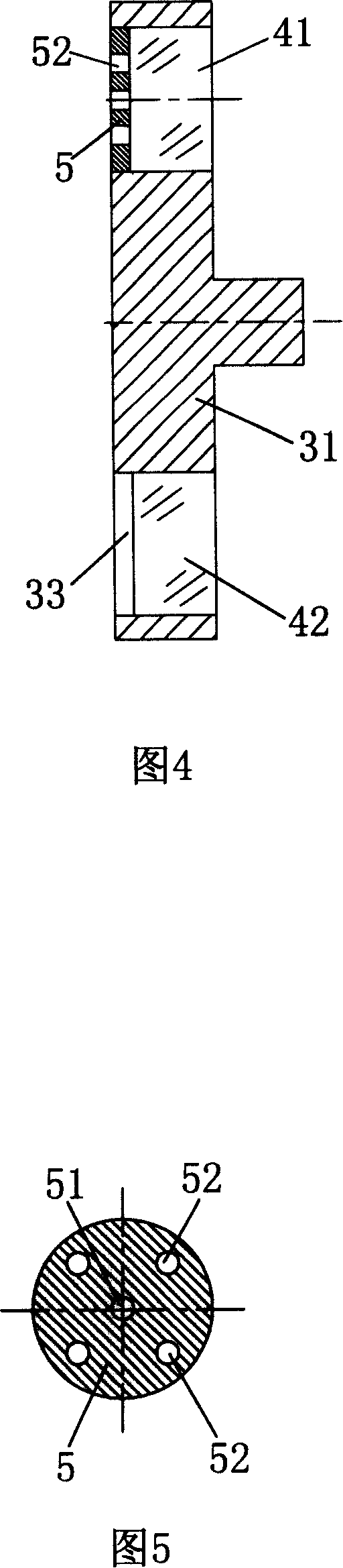
[0023] Please refer to Fig. 1 to Fig. 5, the spectrophotometric detection optical system of microplate reader of the present invention comprises polychromatic light source 1, lens 2, filter wheel 3, optical fiber transmission light beam 6, light colorimetric unit 7, photodetector 8 and control And signal processing unit 9. The polychromatic light source 1 is a halogen tungsten lamp, which is used to generate polychromatic light. The lens 2 is located between the tungsten-halogen lamp 1 and the filter wheel 3 . The filter wheel 3 includes a rotating wheel 31 and a plurality of filters 4 . The rotating wheel 31 is driven by a stepping motor and can rotate around its own axis, and a plurality of installation holes 32 are evenly distributed on the same circumference of the rotating wheel. There are multiple optical filters 4, the number of which is at most consistent with the number of mounting holes 32. The filter 4 includes a plurality of long-wave filters 41 and a plurality ...


PUM


Abstract

The present invention discloses an optical system for ELISA spectrophotometry detection, which comprises a polychromatic light source, a lens, a filter plate wheel, a fiber beam transmission, a photocolorimetry unit, a photoelectric detector, a control unit and a signal processing unit. Wherein, the filter plate wheel is composed of a turning wheel, at least one long wave filter plate and one short wave filter plate arranged on the turning wheel. A front surface of the long wave filter towards the lens is glued with a light diaphragm. The light diaphragm is arranged with a plurality of scattered holes. These scattered holes correspond to lights from different visual fields and enables lights of different visual fields to take part in imaging, thus ensuring evenness of light spot on the imaging. In addition, the light diaphragm on the front surface of the long wave filter plate ensures energy match between long wave signal and short wave signal.

Description

technical field [0001] The invention relates to a spectrophotometric detection optical system of a microplate reader. Background technique [0002] In the spectrophotometric detection optical system of the microplate reader, it is necessary to ensure that the analog signal after photoelectric conversion matches the ADC range of the detection circuit, and the energy difference between the long-wavelength and short-wavelength optical signals is large (up to 20 times), but due to the long and short wavelengths share the same circuit processing module, so the circuit cannot adjust the difference in energy between long and short wavelengths; at the same time, the optical colorimetric part of the microplate reader system has multiple colorimetric channels, and the matched optical path system The image plane spot is required to be uniform to ensure the consistency of multiple channel outputs. [0003] In order to solve the above problems, it is necessary to match the energy of the...

Claims


Application Information

Patent Timeline
Patent Type & Authority Applications(China)
IPC IPC(8): G01N21/27G01N21/01G01N33/53G02F1/23G02F1/29
CPCG01J3/0243G01J2003/1217G01N2201/0453G01J3/51G01J3/12
Inventor 周丽华邱金宏
Owner SHENZHEN MINDRAY BIO MEDICAL ELECTRONICS CO LTD
Why Eureka
Try Eureka