Diffraction grid array external cavity semiconductor laser linear array and method of producing the same

A diffraction grating and semiconductor technology, applied in semiconductor lasers, semiconductor laser devices, lasers, etc., can solve the problems of complex optical path adjustment, low output power, and difficult adjustment, and achieve the effects of simple optical path adjustment, high output power, and easy processing.

Inactive Publication Date: 2008-03-12
CHANGCHUN INST OF OPTICS FINE MECHANICS & PHYSICS CHINESE ACAD OF SCI
View PDF2 Cites 25 Cited by
  • Summary
  • Abstract
  • Description
  • Claims
  • Application Information

AI Technical Summary

Problems solved by technology

The disadvantage of this solution is that due to the grating Littmann structure, when the light is reflected by the mirror and then incident on the grating for the second diffraction, the zero-order diffracted

Method used


Image

  • Diffraction grid array external cavity semiconductor laser linear array and method of producing the same

Examples


Embodiment

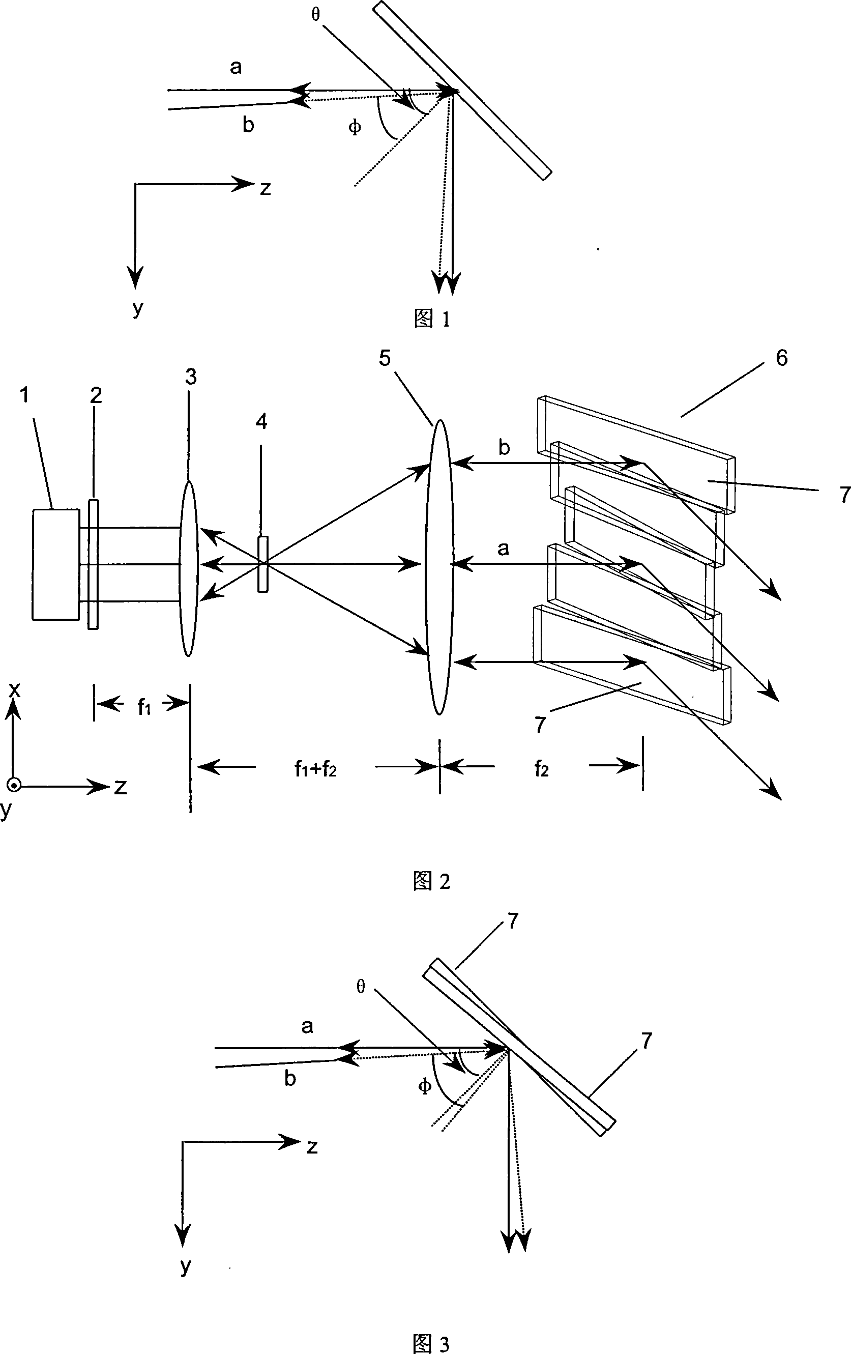
[0020] The specific parameters of the embodiment are as follows: the length of the semiconductor laser line array 1 is 5mm, the center wavelength is 808nm, and there are 5 light-emitting units. After the light emitted is collimated by the fast-axis collimator mirror 2, the fast-axis direction (y direction) is approximately parallel Light. The fast axis collimating mirror 2 is a microcylindrical lens. The focal length of the small lens 3 is f 1 =20mm, caliber D 1 = 10mm, large lens 5 focal length f 2 =100mm, caliber D 1 =40mm, the distance between the small lens 3 and the fast axis collimating mirror 2 is 20mm, the small lens 3 and the large lens 5 are confocally placed to form an inverted telescopic system, which is used to compress the slow axis (x direction) divergence angle, due to the inverted telescopic The system magnification is 5, so the divergence angle of the slow axis is compressed by 5 times. The distance between the diffraction grating array 6 and the large l...


PUM


Abstract

A semiconductor laser linear array of the iffraction grating array exocoele and its preparation method is provided, which belongs to the field of semiconductor laser and comprises a semiconductor laser linear array, a fastaxis collimation lens, a slow lens, a half wave plate, a high-aperture lens and an iffraction grating array. The said semiconductor laser linear array is characterized in making exocoele feedback through the iffraction grating array to make one or more luminescent units of the semiconductor laser linear array incident onto the corresponding iffraction grating unit. By adjusting each of the iffraction grating units, the central wavelength of the luminescent unit in different degrees of crook through the iffraction grating unit and the feedback light retraced back are equal or closely similar with each other, thus the whole spectral line width is reduced. The invention has the advantages of using a plurality of small-area gratings, low cost, easy processing, simple light path adjustment and high output power.

Description

Technical field: [0001] The invention belongs to the field of semiconductor lasers, and relates to an external-cavity semiconductor laser line array for improving spectral line broadening caused by the bending of a light-emitting unit of the semiconductor laser line array. Background technique: [0002] There is inherent thermal stress in the process of bonding the laser line array with the heat sink, so that each light-emitting unit in the line array is not on a straight line and bends. In US 6,584,133, when the entire diffraction grating external cavity feedback is used for spectral compression, as shown in Figure 1, the light beam a emitted by the light-emitting unit on the optical axis (z-axis) and the light beam b emitted by the off-axis light-emitting unit are incident on the grating at different angles. When the diffraction grating is a Littrow structure, the central wavelength of the feedback light returned from the original path is different, so the central waveleng...

Claims


Application Information

Patent Timeline
IPC IPC(8): H01S5/40H01S5/00
Inventor 邓鑫李王立军刘云
Owner CHANGCHUN INST OF OPTICS FINE MECHANICS & PHYSICS CHINESE ACAD OF SCI
Why Eureka
Try Eureka