Inductive energy storage commutation cutoff thyristor method and power converter

A thyristor and converter technology, applied in the field of power conversion, can solve problems such as limited use, impact on the efficiency of the whole machine, and difficulty in engineering implementation.

Inactive Publication Date: 2008-03-12
吴炎喜
View PDF0 Cites 5 Cited by
  • Summary
  • Abstract
  • Description
  • Claims
  • Application Information

AI Technical Summary

Problems solved by technology

The disadvantages of this type of power inverter are: 1. The LC discharge pulse current is large, the oscillation voltage is high, and the discharge pulse will generate a large electrical stress on the SCR, which deteriorates the working conditions of the device, especially for large-capacity devices. 2. The commutation process is limited by the LC charge-discharge time constant and the off-time of the SCR device. The operating frequency of the device should not be high, which limits the The performance of the device is improved. 3. The converter energy storage capacitor needs to use a non-inductive pulse capacitor with a high discharge rate and a low loss angle, which is expensive, and the capacitor is large in size, occupying a considerable position in the device, making the device bulky. 4. The commutation capacity mainly depends on the commutation capacity. In the parameter selection, the value is often small, and the commutation capacity is not enough when the load is started and overloaded, and reliable operation cannot be guaranteed. When the value is large, the light-load commutation is too strong. , the commutation los

Method used


Image

  • Inductive energy storage commutation cutoff thyristor method and power converter
  • Inductive energy storage commutation cutoff thyristor method and power converter
  • Inductive energy storage commutation cutoff thyristor method and power converter

Examples


Embodiment Construction

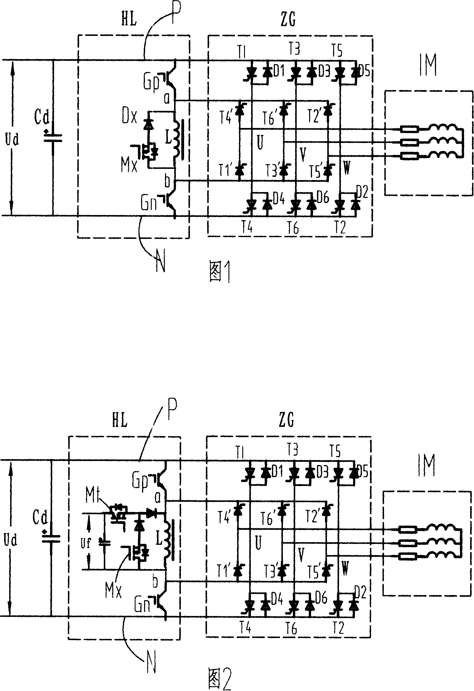
[0027]Referring to Fig. 1, the first embodiment of the present invention: a schematic diagram of the main circuit of a self-injection inductor energy storage commutated three-phase thyristor inverter, and the self-injection inductor energy storage commutator three-phase thyristor inverter is used as an inductor energy storage commutator thyristor The basic structure of the inverter, hereinafter referred to as the basic inductor energy storage commutated three-phase thyristor inverter, which includes the main circuit DC main power supply Ud, self-injection inductor energy storage converter unit HL, main power conversion unit ZG, and three-phase load IM. The basic self-injection inductor energy storage converter unit HL is composed of high-end electronic switch Gp, energy storage inductor L, low-end electronic switch Gn, freewheeling electronic switch Mx, and backstop power diode Dx; the inductor energy storage converter unit HL The collector of the high-end electronic switch Gp...


PUM


Abstract

The utility model relates to a method and a power converter for inductance energy conservation current converting shut off thyristor, belonging to the technical filed of power converting. The utility model comprises an inductance energy storing current converting cell HL which consists of an energy storing inductance L, a high-end electric switch Gp, a low-end electric switch Gn and an after-low electric switch Mx; and a main power converting cell ZG which consists of a main thyristor T, an after-flow power diode D and an assistant thyristor T1. when in current converting, the flow path of the energy storing inductance L current IL is controlled through the electric switch of the inductance energy storing current converting cell HL and the assistant thyristor T1 of the main power converting cell ZG, so that the main thyristor T which needs to be shut off by the main power converting cell ZG is arranged reversely to be shut off. As the utility model converts current through a plurality of main power converter cells of a current converter with a multiple structure, the utility model reduces the cost of the inductance energy conservation current converting cell. The utility model is suitable to be used in various large capacity and low cost power converters which are mainly made of thyristors.

Description

technical field [0001] The invention belongs to the technical field of power conversion, and in particular relates to a method for turning off a thyristor and a power converter thereof. [0002] Power inverters are the basic components of modern industry. Various power converters can be formed on the basis of inverters, which are widely used in AC and DC transmission, wind power generation, ship propulsion and electric locomotive traction, reactive power compensation in power systems, etc. In all fields of national economic construction, it is of great significance to develop high-performance and low-cost power inverters. Background technique [0003] There are two main types of technologies that can constitute the main circuit of the inverter: one is the thyristor power converter with capacitive energy storage LC oscillation forced commutation, and the other is the use of gate self-turn-off devices GTO, GTR, IGBT, A power converter composed of gate fully controlled devices...

Claims


Application Information

Patent Timeline
IPC IPC(8): H02M7/48H02M7/505H02M7/515H02M7/521
Inventor 吴炎喜
Owner 吴炎喜
Why Eureka
Try Eureka