
System for fastening two components on the motor fuel tank, method of fastening by means of this fastening system, and fuel system
A technology for fuel tanks and components, which is applied in the field of fuel systems, and can solve the problems of local over-thickness, time-consuming, and excessive material consumption, etc.
- Summary
- Abstract
- Description
- Claims
- Application Information
AI Technical Summary
Problems solved by technology
Method used
Image

Examples
no. 1 Embodiment approach
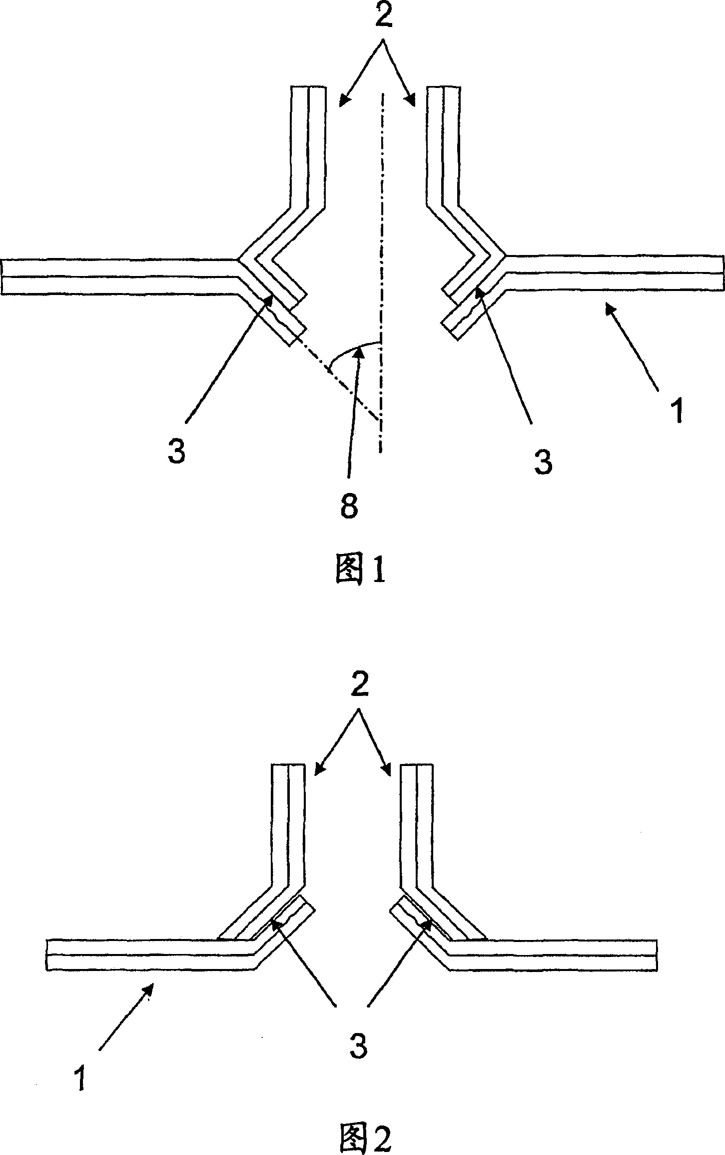
[0044] Figure 1 shows a first specific embodiment of the invention: the multilayer wall (1) of the box has an opening whose profile has a conical shape towards the inside of the box. Angle (8) is the angle of the tapered surface. The multilayer nozzle (2) has an end whose profile matches the profile of the opening in the tank in such a way that the outer layer of the nozzle is welded to the tank at the opening along the weld zone (3) on the outer layer.
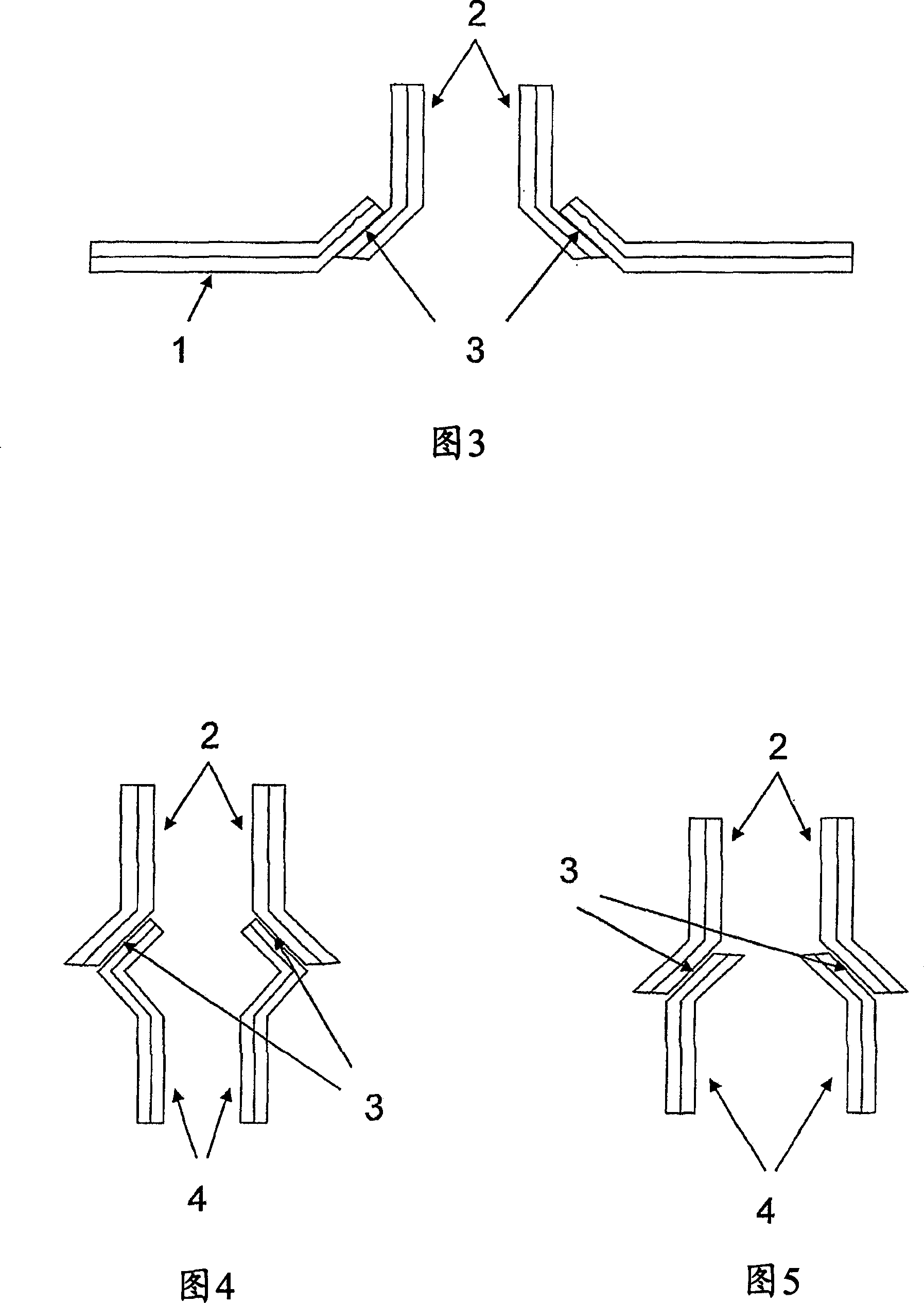
[0045] Figures 2 and 3 show two further embodiments in which the nozzle (2) is welded in such a way that the inner layer of the nozzle (2) is welded to the outer layer of the tank wall (1) (Fig. 2), or weld the outer layer of the nozzle (2) to the inner layer of the wall (1).
[0046] Figures 4 and 5 show the welding of two nozzles, one of which is actually formed by a tubular protuberance of the fuel tank (not shown in these figures). In both cases, there is an overlap in the welding area of the inner layer of the nozzl...
PUM
 Abstract
Description
Claims
Application Information