[0017]A circuit according to the invention provides great flexibility in obtaining a load current in accordance with the set current value. From the outside, the driver circuit only needs the provided set current value. The
microcontroller takes care of providing, for each state of operation, the corresponding control for the two elements, namely the switching converter and the linear
current driver. The combination of these two allows to benefit both from the excellent dynamic properties of the linear current driver, and from the reduce losses at the switching converter. Still, external control of the circuit is very easy.
[0020]One of the preferred embodiments relates to control within the steady portions. Here, during at least a part of the steady portions (preferably a central part, i.e. not directly bordering on a change portion), control is effected to minimize a voltage over the linear current driver. This is due to the fact that the linear current driver, if it effectively limits the load current by increasing the
voltage drop at the amplification element, introduces high losses. While such losses may be tolerated for a short time, e.g. within the change portions and in limited time periods before and / or after, they should be minimized over a long term. Thus, minimizing the
voltage drop over the linear current driver will significantly limit these losses. Preferably, however, minimization is performed such that a
lower limit value (minimum threshold value) for the voltage is maintained, allowing the linear current driver to still operate within its
linear range. This control behavior is achieved by the corresponding control program. Preferably, as will be further explained with relation to preferred embodiments, the minimum threshold value may be calculated such that a minimum voltage remains for operation of the amplification element within the linear current driver. The minimum threshold value may thus be calculated dependent on the load current. Alternatively, it is possible to determine a fixed value for the minimum threshold value, and to store this value in (or make it accessible to) the control means.
[0023]While this is also true for changes where the set current value decreases in the change portion, it is especially applied for change portion during which the set current value rises. If, for example in a pulse application, the set current value rises and then remains constant in a following steady portion, the control program may provide a higher desired switching output voltage before and during the change portion so that e.g. an output
capacitor is charged and the linear current driver may operate in the
linear range also for the higher set current value. Then, within the steady portion, (at least during a later part of the steady portion) the desired output switching value is again lowered, as described above, to limit losses in the linear current driver.
[0025]The storage means may be pre-programmed with predetermined values. According to a further preferred embodiment, however, it is preferred to have the program store values determined during control. It is further preferred to use the stored values during control as starting values only, and determine appropriate values by subsequent closed-
loop control. The thus given values then may be stored in the storage means to update previous values. In this way, the storage is always kept updated, such that any changes in the
driving circuit and / or the load may be compensated.
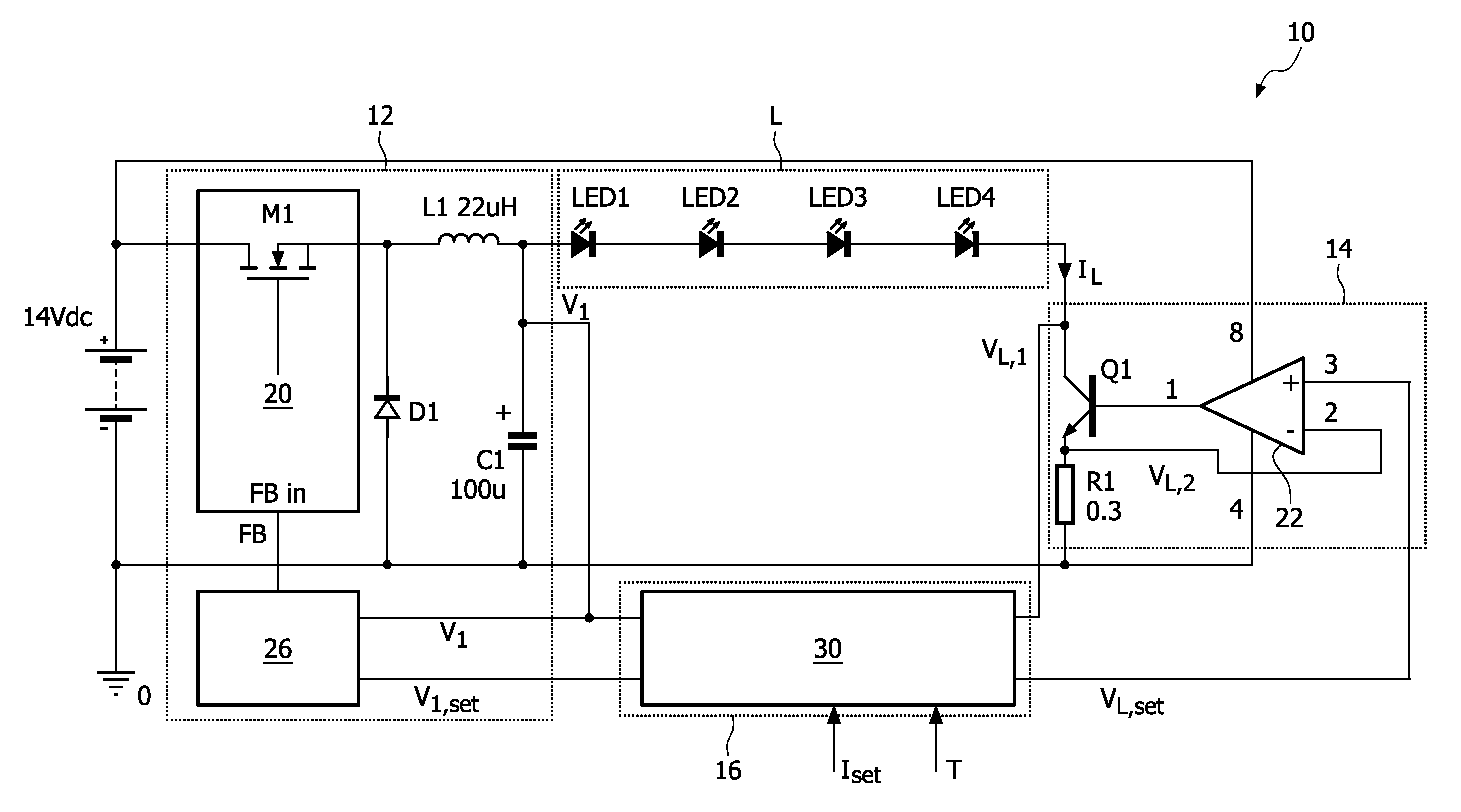
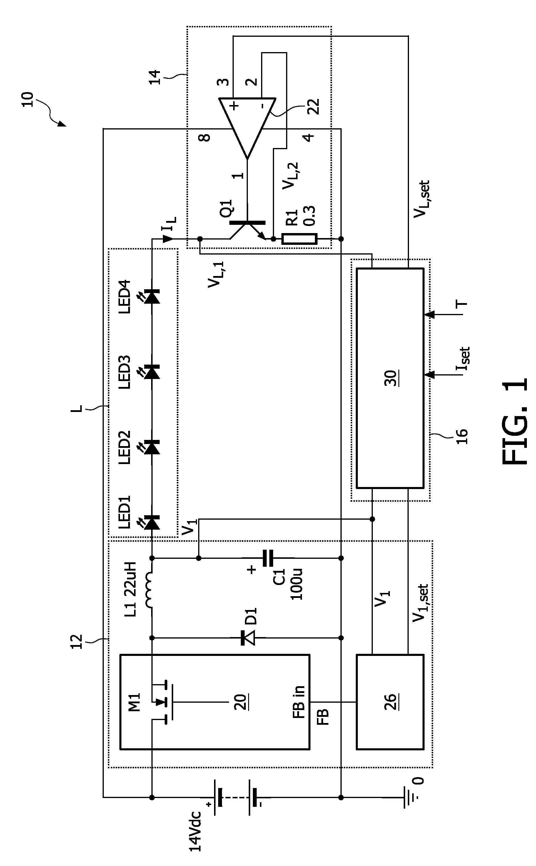
[0027]While for the plurality of branches there is only one switching converter, each
branch has an individual linear current driver circuit connected in series to the terminal. Also, there is an individual sensing input in each of the branches. Accordingly, the
control unit will have (direct or multiplexed) input terminals for the sensing input from each of the branches. In this way, multiple loads can be very effectively driven by a circuit with low part count, where only one switching converter and only one
control unit with
microcontroller is used for a plurality of loads. There may be any number, such as 2, 3 or more loads connected. The loads may be driven simultaneously, but for some applications—such as sequential color rendering in projection applications—it is preferred to drive the loads sequentially.

