Surgical binding instrument binding mechanism

A stapler and surgical technology, applied in the field of medical devices, can solve problems such as failure of surgery, difficulty in withdrawing the nail anvil, increase the area of ​​tissue being punched, etc., so as to facilitate rapid recovery, reduce the chance of damaging the anastomotic ring, and increase conditioning effect of time

Active Publication Date: 2008-03-19
TOUCHSTONE INTERNATIONAL MEDICAL SCIENCE CO LTD
View PDF0 Cites 790 Cited by
  • Summary
  • Abstract
  • Description
  • Claims
  • Application Information

AI Technical Summary

Problems solved by technology

In order to ensure the quality of the anastomosis, two rows of nails are usually arranged in a staggered manner to anastomose the tissue. Although the anastomosis is reinforced, it also increases the area of ​​the tissue that is punched, making it difficult for the tissue to recover quickly
A big disadvantage of this method is that it is difficult to withdraw the anvil, and the anastomotic ring will be damaged if you are not careful, resulting in anastomotic leakage, massive bleeding, and failure of the operation.

Method used


Image

  • Surgical binding instrument binding mechanism
  • Surgical binding instrument binding mechanism
  • Surgical binding instrument binding mechanism

Examples


Embodiment 1

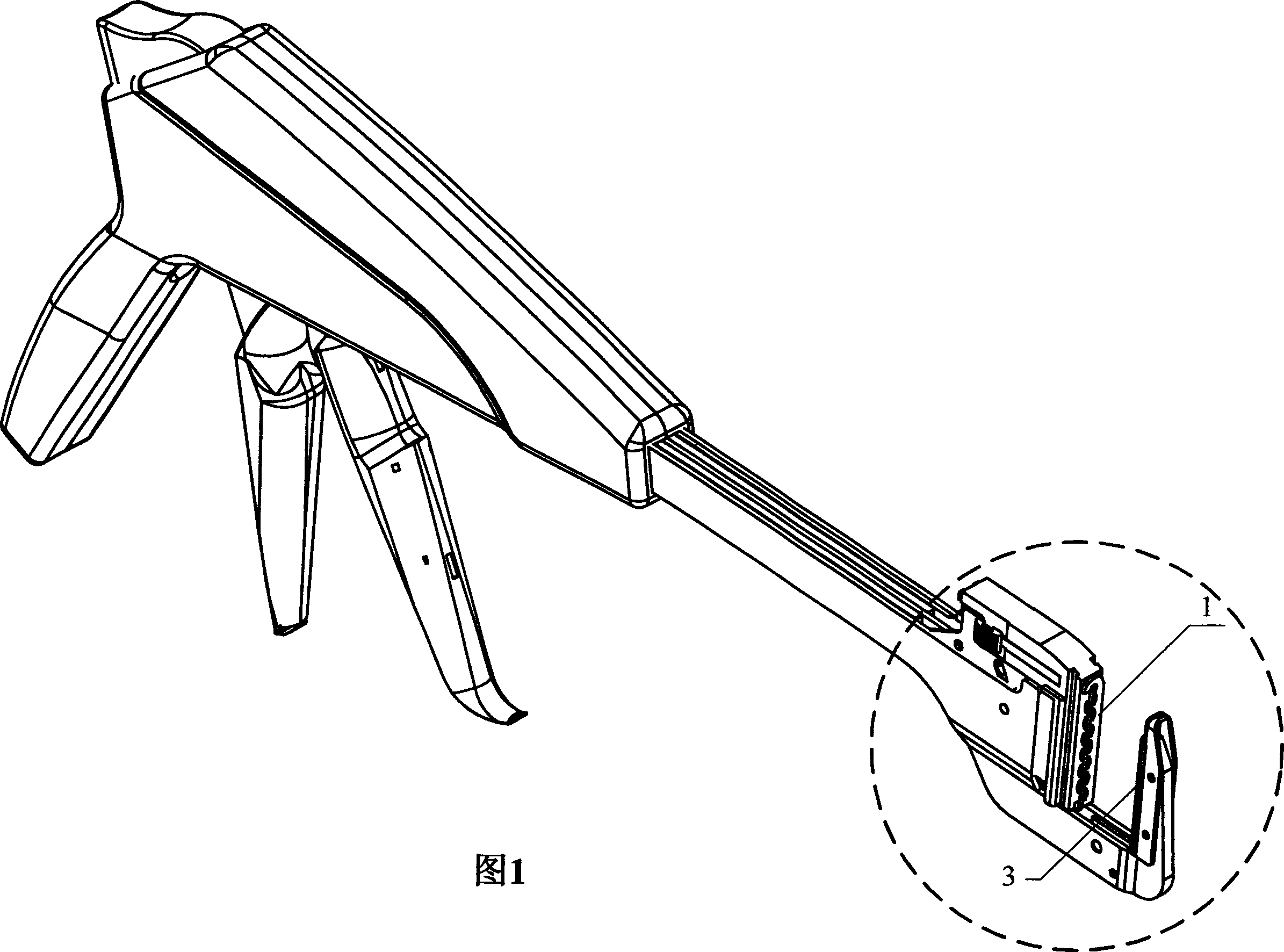
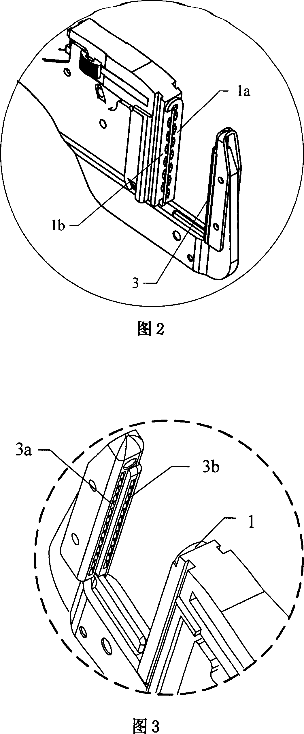
[0030] The stepped binding mechanism shown in Figures 1-3 includes a staple bin 1, a nail pusher 2 and an anvil 3, the nail pusher 2, and the staple bin 1 are installed in the body of the binding instrument, and the nail anvil 3 and the pusher The positions of the nail pieces 2 are corresponding, wherein: the working surfaces of the nail cartridge 1, the nail pushing piece 2 and the nail anvil 3 are not on the same horizontal plane, and at least present a step-like drop distribution structure, and the aforementioned steps are linear steps. That is to say, the staple cartridge 1, the nail pusher 2 and the nail anvil 3 are all linear, and more specifically, the distribution of the staple cartridge 1 and the nail pusher 2 is a linear step with a low inside and a high outside. The distribution of the corresponding nail anvil 3 is a linear step with a high inside and a low outside. It can be seen from Fig. 2 and Fig. 3 that the staple cartridge 1a is higher than the staple cartrid...

Embodiment 2

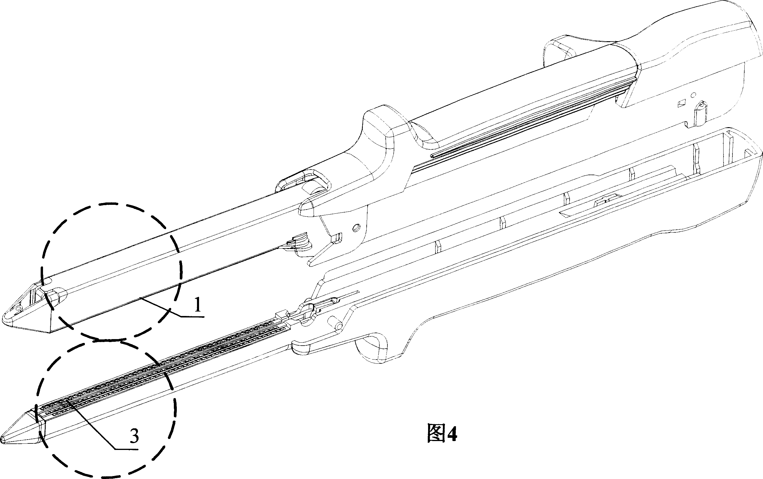
[0033] The stepped binding mechanism shown in Figures 4-6 includes a staple bin 1, a nail pusher 2 and an anvil 3, the nail pusher 2, and the staple bin 1 are installed in the body of the binding instrument, and the nail anvil 3 and the pusher The positions of the nail pieces 2 are corresponding, wherein: the working surfaces of the nail cartridge 1, the nail pushing piece 2 and the nail anvil 3 are not on the same horizontal plane, and at least present a step-like drop distribution structure, and the aforementioned steps are linear steps. That is to say, the staple cartridge 1, the staple pusher 2 and the staple anvil 3 are all linear and bilaterally symmetrical. More specifically, the distribution of the anvils 3 is that the middle two rows are higher than the two outer layers, as shown in Fig. 6, the anvils 3a, 3b are higher than the anvils 3c, 3d. The overall shape is "convex", which is opposite to the distribution of the corresponding staple cartridges 1 and pusher piece...

Embodiment 3

[0035] The stepped binding mechanism shown in Figures 7-10 includes a staple bin 1, a nail pusher 2 and an anvil 3, the nail pusher 2, and the staple bin 1 are installed in the body of the binding instrument, and the nail anvil 3 and the pusher The positions of the nail pieces 2 are corresponding, wherein: the working surfaces of the nail cartridge 1, the nail pushing piece 2 and the nail anvil 3 are not on the same level, and at least present a step-like drop distribution structure, and the aforementioned steps are circular arcs shaped steps, and finally formed into a closed circle. That is to say, the staple cartridge 1 presents a closed circle with stepped distribution, and the inner circle is lower than the outer circle, that is, the staple cartridge 1 a is lower than the staple cartridge 1 b as shown in FIG. 9 . Similarly, the pusher piece 2 also presents a closed circle with stepped distribution, and the inner ring is lower than the outer ring, that is, the pusher piece ...


PUM


Abstract

The invention relates to a binding mechanism of a surgical binding apparatus, which is placed at the head of the surgical binding apparatus and includes a nail pin, a nail pushing plate and a nail block. The nail pushing plate and the nail pin are installed inside the binding apparatus body. The positions of the nail block and the nail pushing plate are opposite. The invention is characterized in that the working faces of nail pin, the nail pushing plate and the nail block are not at the same plane and at least present a step-type fall distributed structure. When the structure is adopted to form an anastomoses opening, the distance between two lines of nails is enlarged; the elasticity of the anastomoses opening which is formed in the operation is increased and is more close to the physiological characteristic of the tissue, which is in favor of the prompt recovery of the tissue. When the nail block is set out from an anastomoses ring or a content object is put through the anastomoses ring after binding, the elasticity of the anastomoses ring becomes larger to allow the nail block or the content object pass through and reduce the probability of damaging the anastomoses ring.

Description

technical field [0001] The invention relates to a binding mechanism, in particular to a surgical binding instrument binding mechanism, which belongs to the field of medical instruments. Background technique [0002] Surgical binding instrument is a modern medical device widely used in end-to-end anastomosis, end-to-side anastomosis, and side-to-side anastomosis of esophagus, stomach, intestine and other digestive tract tissues with other organs. , Linear binding instrument, side-to-side binding instrument, anal hemorrhoid ring cutting mucosa binding instrument, arc-shaped closer and arc-shaped cutting and stapler. Their production greatly reduces the time spent on the operating table by the doctor, improves the work efficiency of the doctor, and more importantly, it brings a qualitative leap in the closure of the anastomotic stoma, which not only makes the anastomotic stoma smooth, but also The anastomosis is very tight, which greatly improves the quality of the anastomosis...

Claims


Application Information

Patent Timeline
Patent Type & Authority Applications(China)
IPC IPC(8): A61B17/072A61B17/138
Inventor 陈望东徐威
Owner TOUCHSTONE INTERNATIONAL MEDICAL SCIENCE CO LTD
Why Eureka
Try Eureka