
Fabric reinforced polyurethane fine sieve and its forming method

A molding method, polyurethane technology, applied in separation methods, chemical instruments and methods, filter screens, etc., can solve the problems of poor flexibility, large quality, and large screen thickness, and achieve good flexibility, small thickness, and small hole width. Effect

Inactive Publication Date: 2008-03-19
ANHUI FANGYUAN PLASTIC & RUBBER
View PDF7 Cites 29 Cited by
  • Summary
  • Abstract
  • Description
  • Claims
  • Application Information

AI Technical Summary

Problems solved by technology

There are thick dividers on both sides of the rectangular screen hole, and reinforcing fibers are laid on the bottom of the thick dividers, which not only improves the mechanical strength of the screen, but also overcomes the problems of large thickness, high quality and poor flexibility of the steel skeleton reinforced polyurethane screen. shortcoming

Method used


Image

  • Fabric reinforced polyurethane fine sieve and its forming method
  • Fabric reinforced polyurethane fine sieve and its forming method
  • Fabric reinforced polyurethane fine sieve and its forming method

Examples


Embodiment 1

[0046] 1) Lay surface-treated reinforcing fibers into the mold cavity at about 85°C, close the mold, seal the joints between the upper and lower templates of the mold, and connect the air suction port to the vacuum equipment.

[0047] 2) Pour the low-viscosity (1.5Pa·s) polyurethane pouring system 1 into the material pot of the pouring machine, heat it to 80°C, and connect each needle valve pouring head of the pouring machine to each gate on the mold respectively.

[0048] 3) Turn on the vacuum equipment. When the vacuum degree reaches 0.09MPa, open the gate located in the middle of the rib, and inject the low-viscosity resin system into the mold cavity under a pressure of 5MPa; after about 20 seconds of pouring, the flow front exceeds both sides When the two gates are opened, the two pouring heads are opened at the same time, and the pouring pressure is also 5MPa.

[0049] 4) After about 1 minute, the resin completely fills the mold cavity. At this time, stop vacuuming, and a...

Embodiment 2

[0052] 1) Lay surface-treated reinforcing fibers into the mold cavity at about 80°C, close the mold, seal the joints between the upper and lower templates of the mold, and connect the air suction port to the vacuum equipment.

[0053] 2) Pour the low-viscosity (0.8Pa·s) polyurethane casting system 2 into the material pot of the pouring machine, heat it to 75°C, and connect each needle valve pouring head of the pouring machine to each gate on the mold respectively.

[0054] 3) Turn on the vacuum equipment. When the vacuum degree reaches 0.08MPa, open the gate located in the middle of the rib, and inject the low-viscosity resin system into the mold cavity under a pressure of 4MPa; after 18 seconds of pouring, the flow front exceeds the When there are two gates, open two pouring heads at the same time, and the pouring pressure is also 4MPa.

[0055] 4) After 50 seconds, the resin completely fills the mold cavity, then stop vacuuming, all gates are still connected to the gates, th...


PUM

PropertyMeasurementUnit
Widthaaaaaaaaaa

Abstract

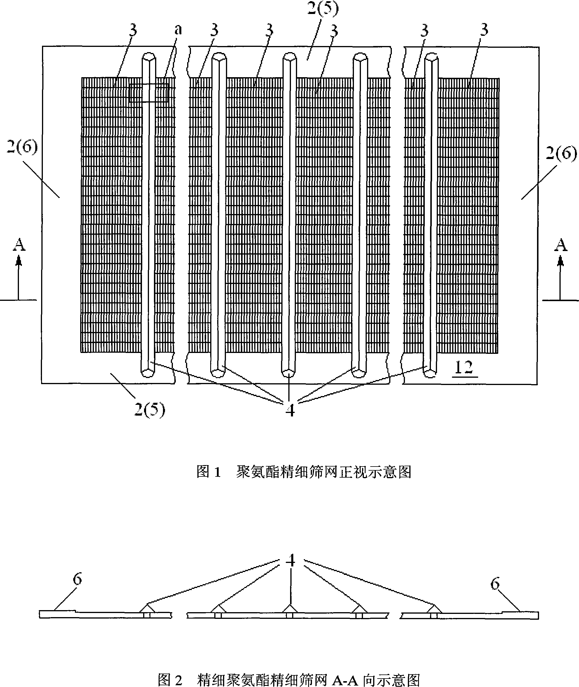
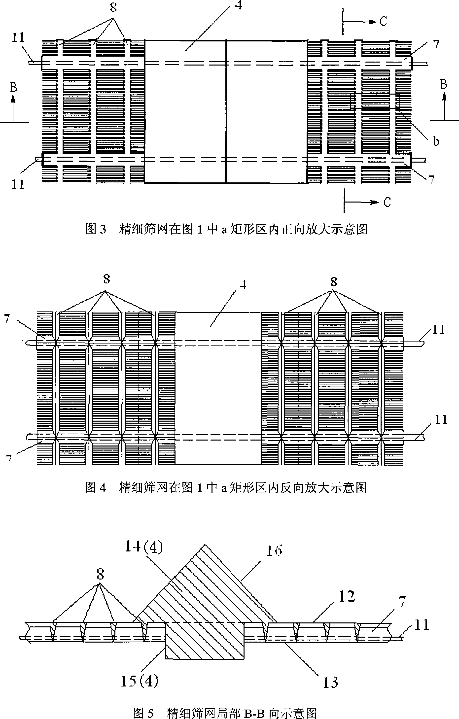
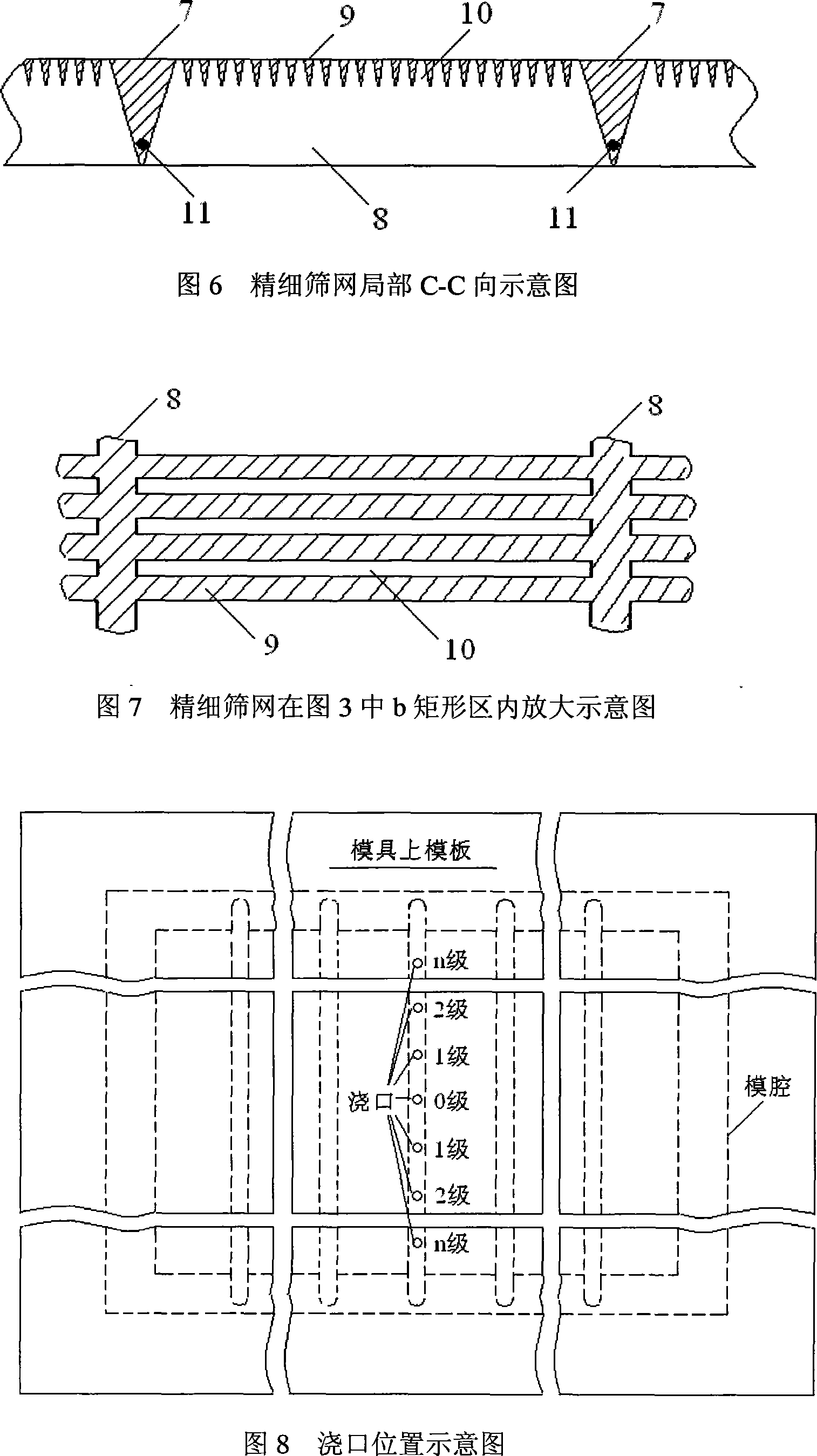
The present invention provides a fiber enhanced polyurethane fine screen and a shaping method. The screen (1) consists of a side frame (2), a screen aperture area (3) and a stiffener (4). The ventilation hole rate is more than or equal to 32 percent. A screen aperture (10) is 1mm-5mm long and 0.1mm-0.5mm wide. A separation strip between holes is 0.1mm-0.5mm thick. Enhanced fibers (11) are laid on the bottom of a thick separation strip (7) to improve the tensile strength of the screen. The screen has the advantages of small thickness, light quality and high opening ratio. The forming of the screen adopts a vacuum auxiliary, multiple-gate and low-viscosity polyurethane system transmission molding method. The method successively injects the low-viscosity polyurethane system in an enclosed vacuum fine screen cavity for curing molding through the multiple ports according to the regulated sequence. The methods of needle valve pouring joints, multiple gates sequence pouring and cavity vacuum pumping are adopted. Multiple streams of material flows can be prevented from meeting to form cavitations. And the problem that an atmospheric pouring method can not form the polyurethane fine screen is solved.

Description

technical field [0001] The invention relates to a fine screen suitable for selecting powder or filtering liquid in the fields of pharmacy, mining, metallurgy, petrochemical industry, water treatment and the like and a forming method thereof. Background technique [0002] There are three important technical indicators for screens for selecting powders or filtering liquids in the fields of pharmaceuticals, mining, metallurgy, petrochemicals, and water treatment: one is the opening ratio, that is, the ratio of the total area of ​​the screen holes to the total area of ​​the screen; The size of the sieve hole, that is, the sieve hole suitable for different sieving levels; the third is the service life. Among them, the larger the opening ratio, the higher the screening efficiency; the shorter the service life, the more frequent the replacement of the screen, affecting production and increasing costs. [0003] Traditional mine fine screens generally use metal woven screens or inje...

Claims


Application Information

Patent Timeline
IPC IPC(8): B07B1/46B01D39/16B29C39/42B29L31/14
Inventor 詹茂盛武京明王凯
Owner ANHUI FANGYUAN PLASTIC & RUBBER
Learn More