Board drilling equipment

A technology for drilling equipment and plates, which is applied to stone processing equipment, stone processing tools, manufacturing tools, etc., can solve problems such as complex procedures, low processing efficiency, and large positioning errors, so as to overcome complex procedures, improve production efficiency, reduce The effect of small positioning errors

Inactive Publication Date: 2008-03-19
裴庭胜
View PDF0 Cites 13 Cited by
  • Summary
  • Abstract
  • Description
  • Claims
  • Application Information

AI Technical Summary

Problems solved by technology

[0006] The purpose of the present invention is to provide a plate drilling equipment through some embodiments, which solves the problems of complex procedures, low processing efficiency and large position

Method used


Image

  • Board drilling equipment
  • Board drilling equipment
  • Board drilling equipment

Examples


Embodiment 1

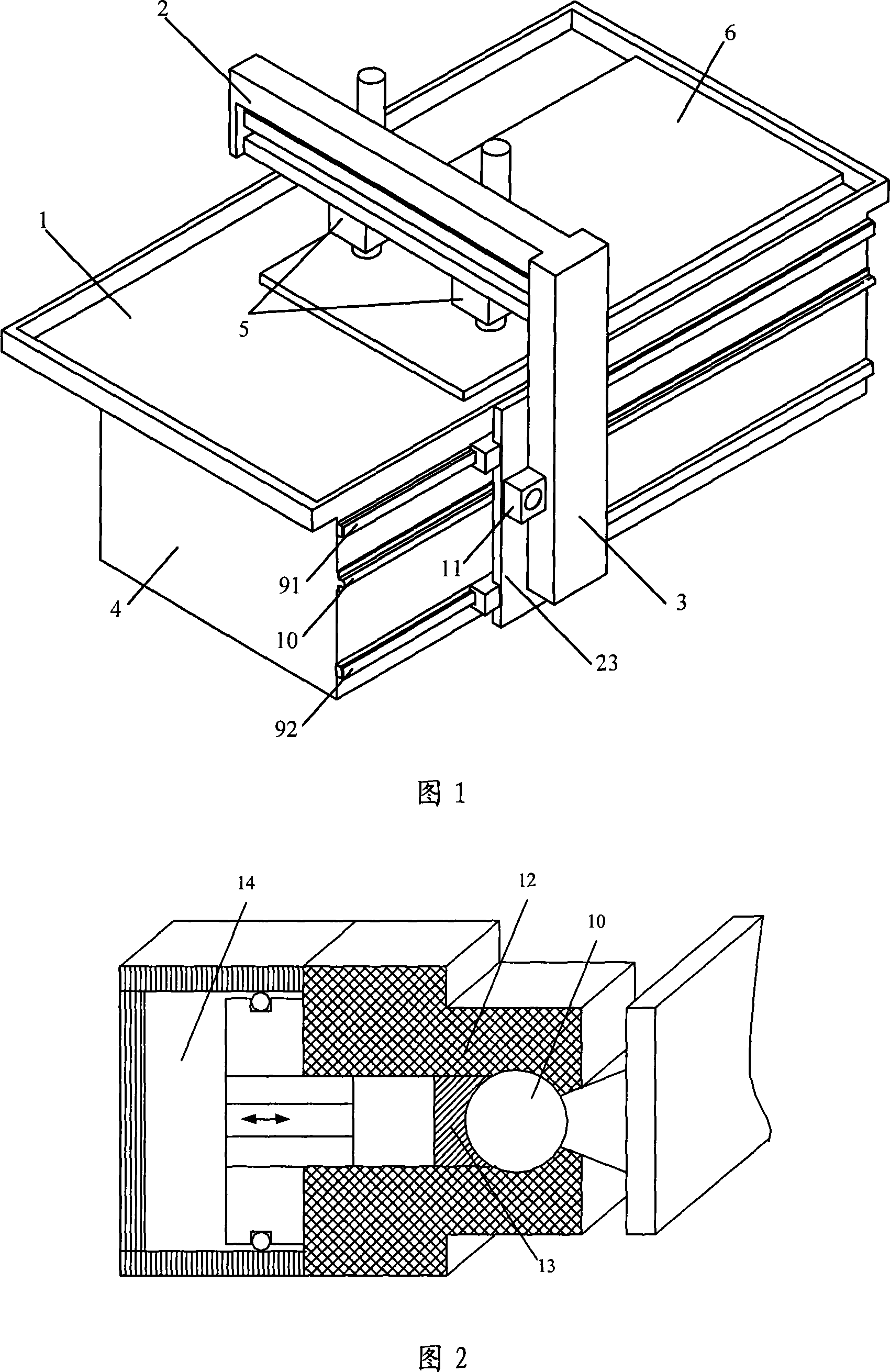
[0027] As shown in Figure 1, it is a structural schematic diagram of a specific embodiment of the plate drilling equipment of the present invention. The equipment of this embodiment includes: a machine bed 4, a workbench 1 arranged on the machine bed 4; connected to the machine bed 4 The frame on the frame is L-shaped and consists of beams 2 and columns 3; two working heads 5 connected to the beams 2 of the frame; The guide rails 91, 92 parallel to the surface of the table 1, the column 3 of the frame and the guide rails 91, 92 are slidingly connected; the machine bed 4 is also provided with a locking guide rail 10 parallel to the guide rails 91, 92, and the locking guide rail 10 is arranged on Between the two guide rails 91, 92, the upright column 3 of the frame is slidably connected with the locking guide rail 10, and a locking device 11 is provided between the upright column 3 and the locking guide rail 10.

[0028] In this embodiment, the frame is composed of a beam 2 and ...


PUM


Abstract

A plate drilling equipment of the invention comprises a machine tool body, an operating floor arranged on the machine tool body, a rack connected with the machine tool body and an operating head section connected with the rack, wherein the rack is an L-shape device and comprises a beam and a pillar. One side of the machine tool body is provided with at least two tracks parallel with the surface of the operating floor. The pillar is connected in sliding with the track. The machine tool body is provided with at least one locking track parallel with the track. The pillar is connected in sliding with the locking track. A locking device is arranged between the pillar and the locking track. The plate drilling equipment of the invention results in an accurate and fast positioning, reduces the required clamping process, improves the production efficiency and adapts to the complex requirement of drilling a plurality of holes in the plate at the same time.

Description

technical field [0001] The invention relates to plate drilling equipment, in particular to a machine tool for drilling plate-shaped stones. Background technique [0002] Existing drilling machine tools for processing stone slabs usually include a machine bed, a workbench fixed on the machine bed, a gantry-shaped frame fixed on the machine bed, and a working machine set on the beam of the frame. The head is the drill head that performs the drilling action. The working head can move horizontally relative to the beam through the guide rail on the beam to adjust the drilling position. [0003] During the working process of the existing drilling machine tool, the stone slab is first placed horizontally on the workbench; To determine the position on the table, locate the stone slab in such a way that the stone slab touches the movable block; after the positioning is completed, use a clamping device to apply a certain pressure from the top or side of the stone slab to clamp the st...

Claims


Application Information

Patent Timeline
IPC IPC(8): B28D1/14
Inventor 裴庭胜
Owner 裴庭胜
Why Eureka
Try Eureka