
Tipping plate energy-saving type multifunctional valve

A multi-functional valve, energy-saving technology, applied in functional valve types, control valves, valve devices, etc., can solve the problems of large floor space, inconvenient maintenance and testing, large valve width, etc. Effects of reduced friction coefficient and reduced external dimensions

Inactive Publication Date: 2008-03-19
ZHUZHOU SOUTHERN VALVE
View PDF0 Cites 6 Cited by
  • Summary
  • Abstract
  • Description
  • Claims
  • Application Information

AI Technical Summary

Problems solved by technology

[0002] In the prior art, the general hydraulic control valve has a structure in which a main valve plate is hinged through a valve shaft in the valve body, and a discharge hole and a small valve plate are arranged on it, and there is a horizontal valve connected to the small valve plate in the valve body. The control rod and the control cylinder connected with the horizontal control rod are set on the side wall of the valve body, and the upper and lower chambers of the control cylinder are respectively connected to the front and rear of the main valve. The pressure difference between the front and rear of the main valve is used to control the pressure difference between the main valve plate and the small valve plate. Fast and slow, to achieve the elimination of pump stop water hammer and non-return function, because the control cylinder is located on the side wall of the main valve, the valve width is large, the floor space is large, and maintenance and testing are inconvenient

Method used


Image

  • Tipping plate energy-saving type multifunctional valve
  • Tipping plate energy-saving type multifunctional valve

Examples


Embodiment 1

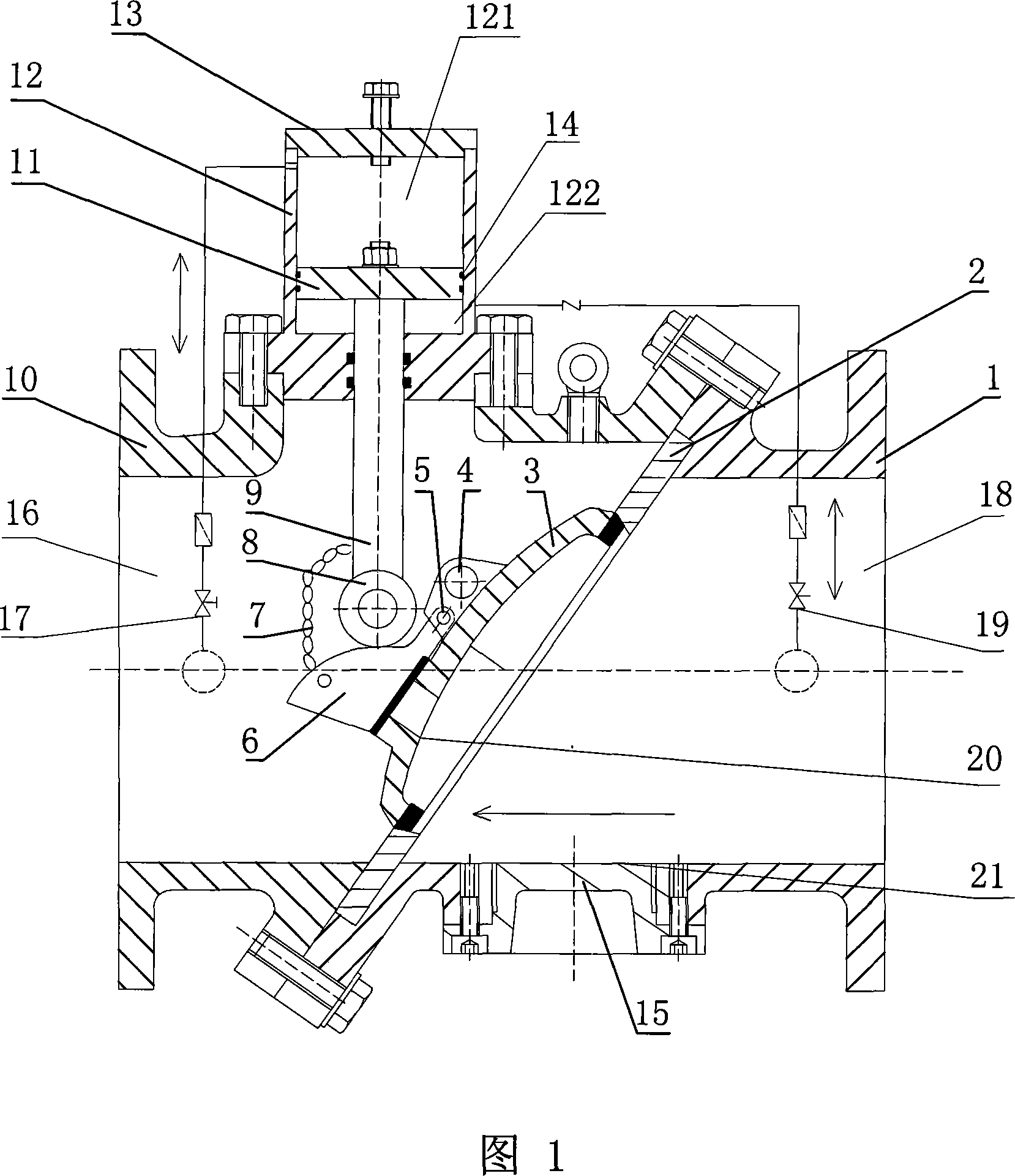
[0034] Embodiment 1: As shown in Figure 1, the inclined plate energy-saving multifunctional valve of the present invention adopts a piston as a control mechanism, which includes a valve body, a valve plate seat 2, a valve plate 3, a cam assembly 6 and a piston 11, and the valve body adopts Split structure, the right valve body 1 and the left valve body 10 are connected by bolts, which is convenient for timely replacement of valve plate 3 seals and other maintenance, and maintenance can be carried out without stopping the machine. The piston cylinder 12 of the piston 11 is fixed on the top of the left valve body 10 , the top of the piston cylinder 12 is provided with a piston cover 13 , and an O-ring 14 is provided between the piston rod 9 and the piston cylinder 12 . The rodless chamber 121 of the piston 11 is provided with an outlet bypass pipe 17 connected to the outlet port 16 of the valve body, and the rod chamber 122 is provided with an inlet bypass pipe 19 connected to th...

Embodiment 2

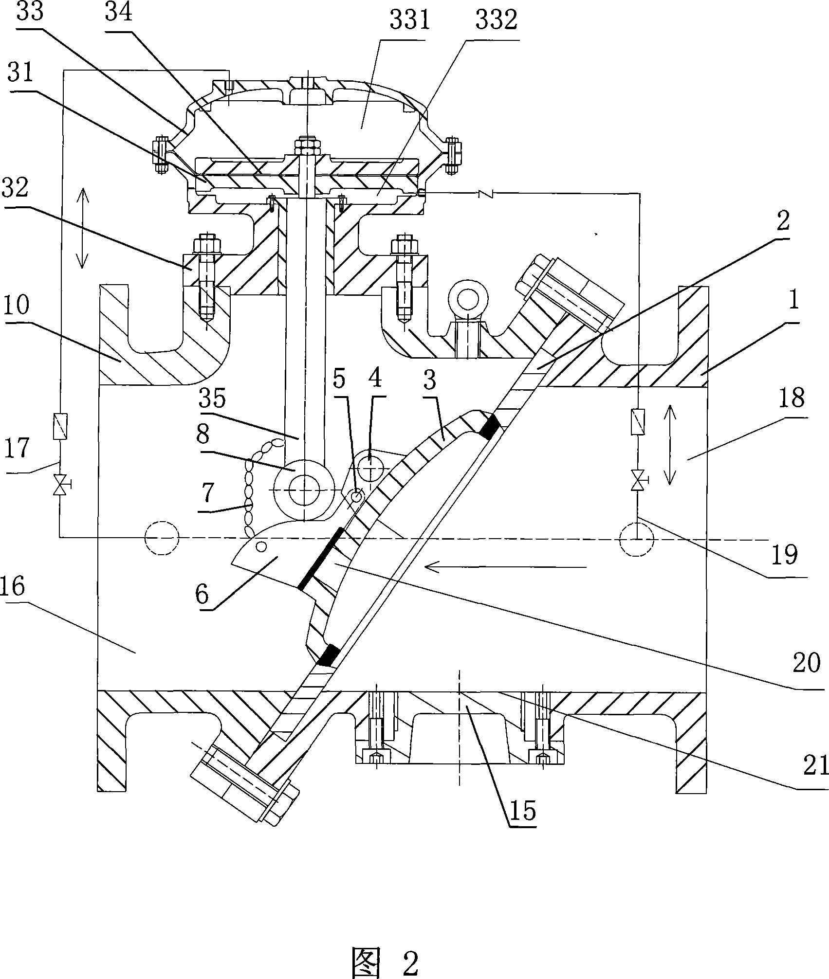
[0037]Embodiment 2: As shown in Figure 2, the control mechanism of the inclined plate energy-saving multifunctional valve of the present invention adopts a diaphragm control mechanism, which includes a valve body, a valve plate seat 2, a valve plate 3, a cam assembly 6, a diaphragm Chamber 33 and the diaphragm 34 set in the diaphragm chamber 33, the valve body adopts a split structure, the right valve body 1 and the left valve body 10 are connected by bolts, which is convenient for timely replacement of valve plate 3 seals and other maintenance without stopping the machine Make repairs. The diaphragm cavity 33 is fixed on the top of the left valve body 10 through the diaphragm seat 32, the diaphragm 34 is fixed on the diaphragm pressure plate 31, and the diaphragm 34 separates the diaphragm cavity 33 into an upper diaphragm cavity 331 and a lower diaphragm cavity 332 , the diaphragm upper chamber 331 is provided with an outlet bypass pipe 17 connected to the outlet port 16 of ...


PUM


Abstract

The invention discloses a sloping plate energy saving type multifunctional valve, which comprises a valve body, a valve plate, a cam component and a controlling mechanism. The valve plate is fixed in the valve body through a valve plate rotating axle, a discharge orifice is arranged on the valve plate, the cam component corresponding to the discharge orifice is fixed on the valve plate through a cam rotating axle, the valve body comprises a right valve body and a left valve body which are connected through bolts, the controlling cavity of the controlling mechanism is fixed at the top part of the left valve body, the controlling cavity is longitudinally divided into an upper controlling cavity and a lower controlling cavity in sequence, an outlet bypass pipe connected with the outlet opening end of the valve body is arranged in the upper controlling cavity, an inlet bypass pipe connected with the inlet opening end of the valve body is arranged in the lower controlling cavity, a rotating wheel contacting with the cam component in a rolling way is arranged at the bottom end of a controlling rod, a chain or a hinge is arranged on the controlling rod, and the other end of the chain or the hinge is connected with the cam component. The invention has the advantages that the structure is simple and compact, the assembly and the maintenance are convenient, the floor space is small, and the security and the reliability are high.

Description

technical field [0001] The invention mainly relates to the field of pump valves, in particular to a slant plate energy-saving multifunctional valve. Background technique [0002] In the prior art, the general hydraulic control valve has a structure in which a main valve plate is hinged through a valve shaft in the valve body, and a discharge hole and a small valve plate are arranged on it, and there is a horizontal valve connected to the small valve plate in the valve body. The control rod and the control cylinder connected with the horizontal control rod are set on the side wall of the valve body, and the upper and lower chambers of the control cylinder are respectively connected to the front and rear of the main valve. The pressure difference between the front and rear of the main valve is used to control the pressure difference between the main valve plate and the small valve plate. Fast and slow, to achieve the elimination of pump stop water hammer and check function. Si...

Claims


Application Information

Patent Timeline
IPC IPC(8): F16K15/18
Inventor 罗建群李剑董真丁文敏
Owner ZHUZHOU SOUTHERN VALVE
Features
  • Generate Ideas
  • Intellectual Property
  • Life Sciences
  • Materials
  • Tech Scout
  • Unparalleled Data Quality
  • Higher Quality Content
  • 60% Fewer Hallucinations
Learn More