Accumulator multi-unit synchronous charging/discharging device and its method

A charging and discharging device, charging and discharging technology, applied in battery circuit devices, secondary battery charging/discharging, circuit devices, etc., can solve the problems of high harmonic content, low power factor, and large power grid pollution, and achieve harmonic content The effect of reducing electricity bills and improving utilization efficiency

Inactive Publication Date: 2008-03-19
BEIJING JIAOTONG UNIV
View PDF0 Cites 27 Cited by
  • Summary
  • Abstract
  • Description
  • Claims
  • Application Information

AI Technical Summary

Problems solved by technology

[0005] First, solve the problem of low power factor and high harmonic content of existing charging and discharging equipment, which will cause serious pollution to the power grid

Method used


Image

  • Accumulator multi-unit synchronous charging/discharging device and its method
  • Accumulator multi-unit synchronous charging/discharging device and its method
  • Accumulator multi-unit synchronous charging/discharging device and its method

Examples


Embodiment Construction

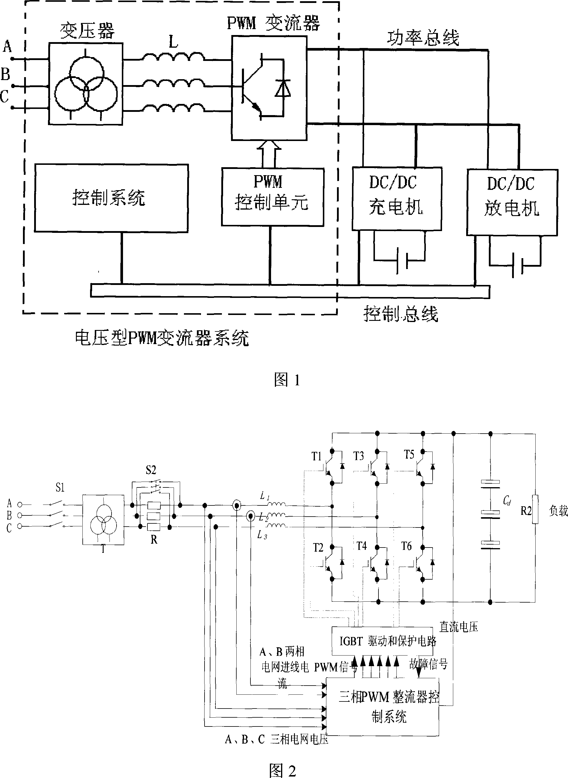
[0025] As shown in Figure 1, the overall scheme of the battery multi-unit synchronous charging and discharging device is shown. The power grid is electrically isolated through a three-phase transformer while providing the required grid-side voltage E. The output of the transformer and the three-phase full bridge are connected through a three-phase power frequency inductor L. . The DC / DC charger, discharger and PWM rectifier are connected through the power bus. The PWM module and the controllers of each DCDC module are connected to the main controller unit through the bus for communication coordination.

[0026] The specific circuit of the pre-stage circuit of the battery multi-unit synchronous charging and discharging device is shown in Figure 2. There is a three-phase contactor S between the power grid and the three-phase power frequency transformer T 1 , used to control the on-off of the main circuit; there is a soft-start resistor R between the transformer and the three-ph...


PUM


Abstract

The invention provides a multi-unit device and a method for synchronically charging and discharging an accumulator. A main controller is respectively connected with a rectification (inversion) unit, a DC-DC converter unit, and an upper computer. The main circuit structure of the main controller comprises a front circuit part and a back circuit part. With the space vector pulse width modulation (SVPWM) technique used in the front circuit part of the inventive device, the power factor is approximately 1 in the charging mode and approximately -1 in the discharging mode, so as to improve the energy utilization efficiency, therefore, reducing the capacity requirement of an isolation transformer, and costs of other hardware. Meanwhile, the harmonic wave content is decreased and the pollution to a power grid is reduced. The device is in parallel connected with a plurality of independent two-way DC-DC converters, when a plurality of groups of battery units are synchronically charged or discharged, the residual electricity released by certain batteries can be charged into other batteries without passing through the power grid, so as to improve the service efficiency of the battery residual electricity and save electricity expenditure.

Description

technical field [0001] The invention relates to a multi-unit synchronous charging and discharging device and method for storage batteries, which can be used for maintenance of storage batteries and belongs to the technical field of storage batteries. Background technique [0002] At present, the high-power battery charging and discharging system still adopts a large number of thyristor phase-shift control technology, changing the conduction trigger angle to change the energy transmission direction and size, converting AC power into DC power during charging, and inverting the remaining power of the battery to the grid or power grid during discharging. It is directly consumed on the resistance, but it cannot discharge other batteries while charging or cannot charge other batteries while discharging. [0003] The existing charging and discharging equipment has some disadvantages: first, the power factor is low, and power margin needs to be considered during design, resulting in...

Claims


Application Information

Patent Timeline
Patent Type & Authority Applications(China)
IPC IPC(8): H02J7/00H02J7/04H02J7/10H01M10/44
CPCY02E60/12Y02E60/10
Inventor 姜久春张维戈冯韬
Owner BEIJING JIAOTONG UNIV
Why Eureka
Try Eureka