Self-excitation full empty core passive compensation pulse generator
A technology for compensating pulses and generators, applied to electrical components, electromechanical devices, etc., which can solve problems such as low power density and energy density, failure to self-excite and start excitation, etc., and achieve the effect of reducing mass, reducing inductance, and increasing speed
- Summary
- Abstract
- Description
- Claims
- Application Information
AI Technical Summary
Problems solved by technology
Method used
Image
Examples
specific Embodiment approach 1
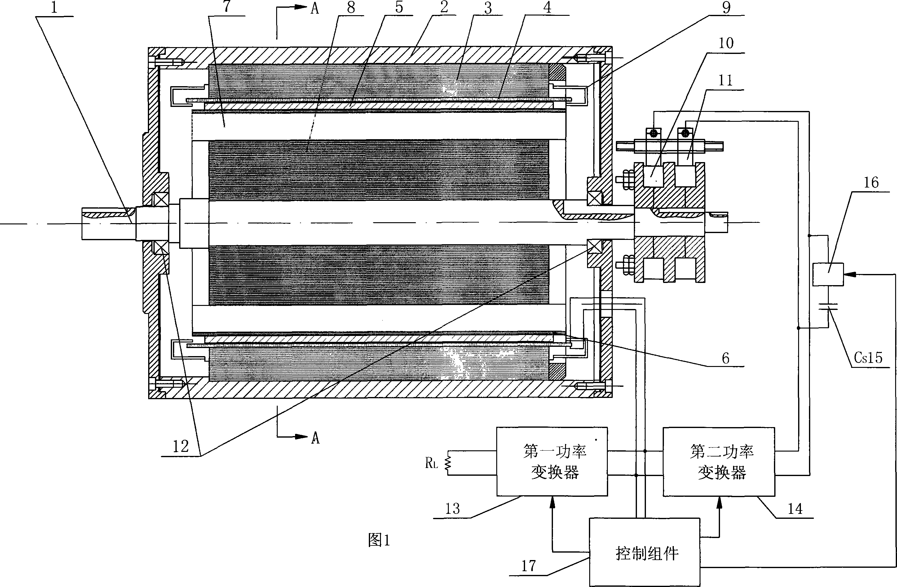
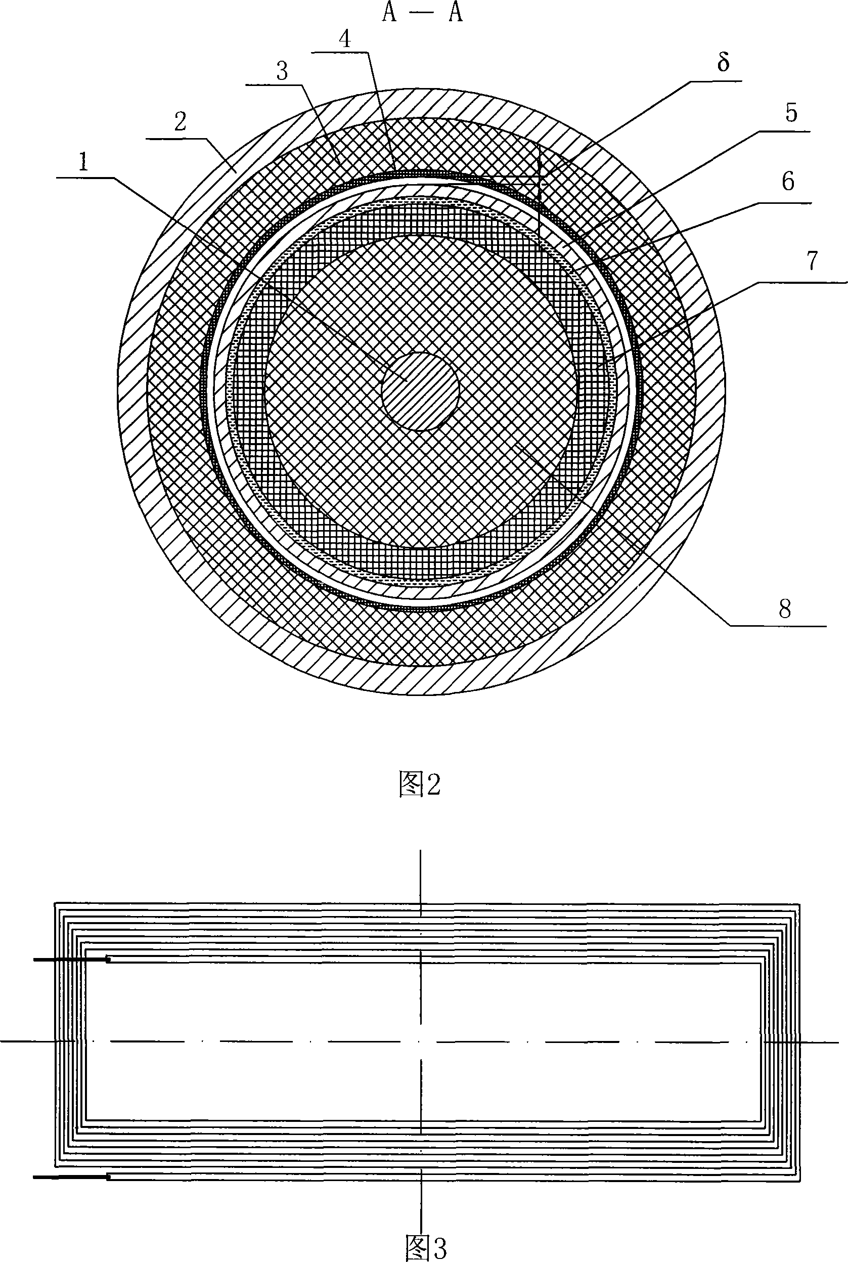
[0011] Specific embodiment 1: This embodiment will be described with reference to Figures 1 and 2. This embodiment is composed of a rotor, a stator, a slip ring 10, a brush 11 and a bearing 12; the rotor is composed of an aluminum compensation cylinder 5, a carbon fiber bandage 6, and a rotor excitation Winding 7, carbon fiber epoxy resin rotor yoke 8 and main shaft 1. A carbon fiber epoxy resin rotor yoke 8 is fixed on the main shaft 1. The outer surface of the carbon fiber epoxy resin rotor yoke 8 is bonded with a rotor field winding 7, and the rotor field winding 7 is outside The lashing is fixed with carbon fiber lashing bandage 6, the aluminum compensation cylinder 5 is sleeved on the outer surface of the carbon fiber lashing bandage 6; the stator is composed of the casing 2, the composite stator yoke 3, the stator slotless armature winding 4 and the shielding box 9, and the composite stator yoke 3 is fixed On the inner wall of the casing 2, the inner wall of the composite st...
specific Embodiment approach 2
[0012] Specific embodiment 2: This embodiment is described with reference to Figs. 1 and 2. The difference between this embodiment and the first embodiment is that it also includes a first power converter 13, a second power converter 14, a starting capacitor Cs15, and a switching device 16. And control assembly 17; the two armature ends of the stator slotless armature winding 4 are respectively connected to the two input ends of the first power converter 13, the two input ends of the second power converter 14 and the two control assemblies 17 Input terminal; the two output terminals of the first power converter 13 are respectively connected to the two power supply terminals of the load 16; one end of the starting capacitor Cs15 is connected to one end of the switching device 16, the other end of the starting capacitor Cs15 and the other end of the switching device 16 are respectively Connect the two ends of the brush 11, the two output ends of the second power converter 14 are als...
specific Embodiment approach 3
[0013] Specific embodiment three: This embodiment is described with reference to Fig. 1 and Fig. 2. The difference between this embodiment and the first embodiment is that there is 0.8mm between the inner surface of the stator slotless armature winding 4 and the outer surface of the aluminum compensation cylinder 5. ~1.2mm air gap. Other components and connection modes are the same as the first embodiment.
PUM
 Abstract
Description
Claims
Application Information
 - R&D
- Intellectual Property
- Life Sciences
- Materials
- Tech Scout
- Unparalleled Data Quality
- Higher Quality Content
- 60% Fewer Hallucinations
Browse by: Latest US Patents, China's latest patents, Technical Efficacy Thesaurus, Application Domain, Technology Topic, Popular Technical Reports.
© 2025 PatSnap. All rights reserved.Legal|Privacy policy|Modern Slavery Act Transparency Statement|Sitemap|About US| Contact US: help@patsnap.com


