Method for welding metal under strong magnetic field circumstance

A welding method and strong magnetic field technology, applied in the direction of welding equipment, welding equipment, auxiliary welding equipment, etc., can solve the problems that metal parts cannot meet the strength requirements, slag inclusions, pores, cracks, and welding quality are easy to appear, and achieve welding Good meat fusion, reduced welding defects, and high welding quality

Inactive Publication Date: 2008-03-26
GUIZHOU BRANCH CHINA ALUMINUM IND
View PDF0 Cites 14 Cited by
  • Summary
  • Abstract
  • Description
  • Claims
  • Application Information

AI Technical Summary

Problems solved by technology

In a strong magnetic field environment such as an aluminum electrolysis workshop, the strong magnetic field during the welding process has a great impact on the welding quality. It is not easy to arc during welding, the fusion of the welded meat is poor, and defects such as slag inclusions, pores, and cracks are prone to occur. The metal parts cannot meet the strength requirements, and there is no reliable on-site welding method in the existing technology except moving the metal to outdoor welding

Method used


Image

  • Method for welding metal under strong magnetic field circumstance

Examples


Embodiment 1

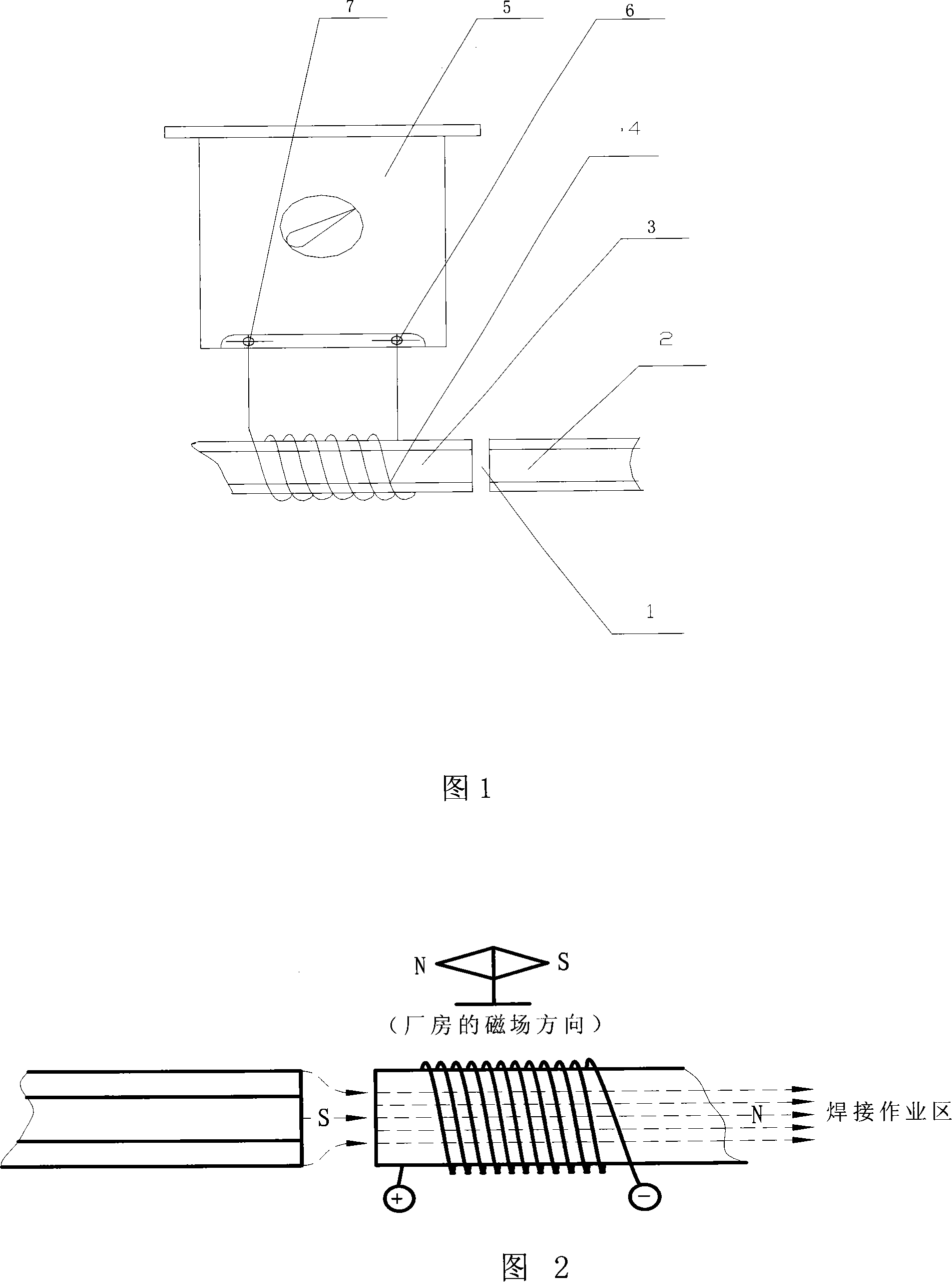
[0015] As shown in Figure 1, wrap the wire 4 of appropriate length on the metal workpiece 2 or metal workpiece 3 to be welded on any side of the metal workpiece welding point 1 with a certain number of turns and direction, and the two ends of the wire 4 are respectively connected to the DC welding machine. The positive terminal 6 and the negative terminal 7 of the DC welding machine are connected together, thus forming a current loop. When the switch of the DC welding machine 5 is turned on, a magnetic field superimposed with a strong magnetic field is generated in the welding area. The field strength at the welding point 1 of the metal workpiece. If the direction of the magnetic field remains unchanged and the strength increases, it indicates that the winding direction of the wire 4 is wrong. Wind the wire 4 in the opposite direction, and then adjust the number of turns of the wire 4 so that the measured field strength is zero; if the field strength decreases or the direction ...

Embodiment 2

[0017] Wrap the wire 4 of appropriate length on the metal workpiece 2 or metal workpiece 3 to be welded on any side of the metal workpiece welding point 1 with a certain number of turns and directions, and the two ends of the wire 4 are respectively connected to the positive terminal 6 of the DC welding machine and the DC welding machine. The negative terminal 7 of the machine wiring is connected, so that a current loop is formed, and the switch of the DC welding machine 5 is turned on, and a magnetic field superimposed with a strong magnetic field is generated in the welding area, and a small steel plate is placed on the side of the metal workpiece 2 or metal workpiece 3 , if the mutual magnetic force between the small steel plate and the metal workpiece 2 or metal workpiece 3 disappears, and the small steel plate does not adhere to the metal workpiece 2 or metal workpiece 3, then the winding direction and the number of turns of the electric wire 4 are appropriate; if the small...


PUM

PropertyMeasurementUnit
tensile strengthaaaaaaaaaa

Abstract

The present invention relates to welding technology, and is especially metal welding method in strong magnetic field environment. The metal welding method in strong magnetic field environment includes measuring the strength and direction of the environmental magnetic field with special instrument, forming one coil of certain turn number and winding direction and connecting the coil to one metal workpiece to be welded, connecting the coil to one DC welder to generate one magnetic field in the same strength as and reverse direction to the environmental magnetic field, and welding with one other welder in no or weak magnetic field condition. The method of the present invention can result in high welding quality, weld seam strength reaching 80 % of mother material strength and tensile strength of the weld seam up to 700 MPa.

Description

technical field [0001] The invention relates to a metal welding technology in the aluminum electrolysis industry, in particular to a metal welding method in a strong magnetic field environment. Background technique [0002] At present, arc welding is mainly used for metal welding. In a strong magnetic field environment such as an aluminum electrolysis workshop, the strong magnetic field during the welding process has a great impact on the welding quality. It is not easy to arc during welding, the fusion of the welded meat is poor, and defects such as slag inclusions, pores, and cracks are prone to occur. The metal parts cannot meet the strength requirements, and there is no reliable on-site welding method in the prior art except moving the metal to outdoor welding. Contents of the invention [0003] The technical problem to be solved by the present invention is to overcome the deficiencies in the prior art, and to provide a welding method that is easy to arc when performi...

Claims


Application Information

Patent Timeline
Patent Type & Authority Applications(China)
IPC IPC(8): B23K37/00B23K9/08H01F13/00
Inventor 周新林王苍海肖述兵张自亮毛亚红龚慧玲
Owner GUIZHOU BRANCH CHINA ALUMINUM IND
Why Eureka
Try Eureka