4f phase coherent imaging device based on michelson interferometer

A phase coherent and imaging device technology, applied in the field of third-order nonlinear refractive index devices, can solve the problems of high noise and laser stability requirements, troublesome data processing of coherent imaging technology, complex data processing, etc., and achieve fast test speed , low stability requirements, and simple data processing

Inactive Publication Date: 2008-03-26
HARBIN INST OF TECH
View PDF0 Cites 9 Cited by
  • Summary
  • Abstract
  • Description
  • Claims
  • Application Information

AI Technical Summary

Problems solved by technology

[0005] The present invention solves the troublesome data processing of the traditional 4f system coherent imaging technology, the unavoidable nonlinear absorption, and the small deformation range of

Method used


Image

  • 4f phase coherent imaging device based on michelson interferometer
  • 4f phase coherent imaging device based on michelson interferometer
  • 4f phase coherent imaging device based on michelson interferometer

Examples


specific Embodiment approach 1

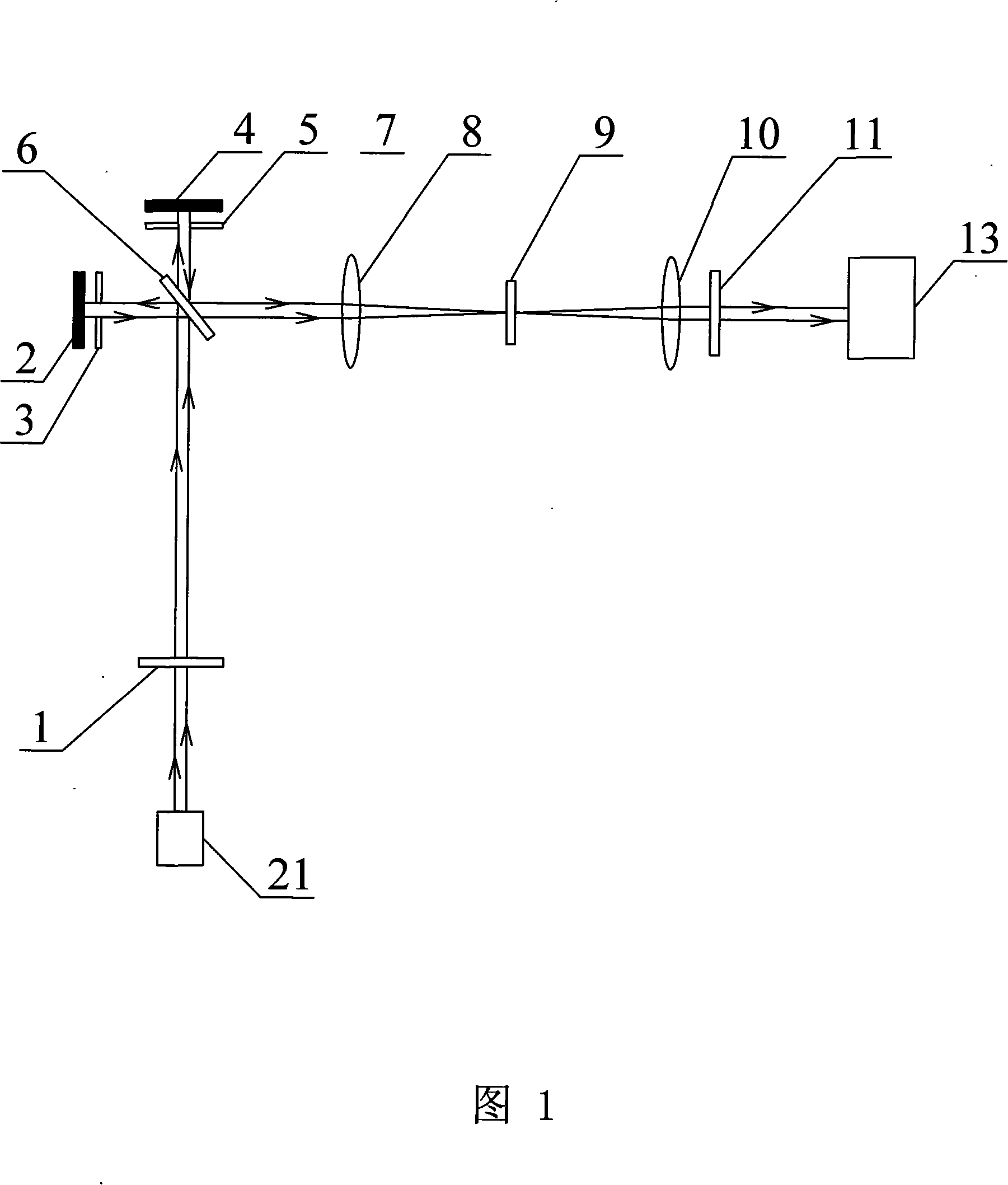
[0012] Specific embodiment 1: Referring to Fig. 1 to Fig. 4, this embodiment consists of a first linear attenuation plate 1, a first total reflection mirror 2, a first aperture stop 3, a second total reflection mirror 4, and a second aperture stop 5 , the first beam splitter 6, the first convex lens 8, the second convex lens 10, the second linear attenuation sheet 11, the CCD camera 13 and the laser 21, the first linear attenuation sheet 1, the first beam splitter 6, the second aperture stop 5 and the second total reflection mirror 4 are all arranged successively on the central axis of the upper side of the emission port of the laser 21, the optical axis axis of the transmitted light of the first linear attenuation plate 1, the center of the light transmission hole of the second aperture stop 5 axis and the central axis of the second total reflection mirror 4 coincide with the central axis on the upper side of the laser emission port of the laser 21, and the right side of the i...

specific Embodiment approach 2

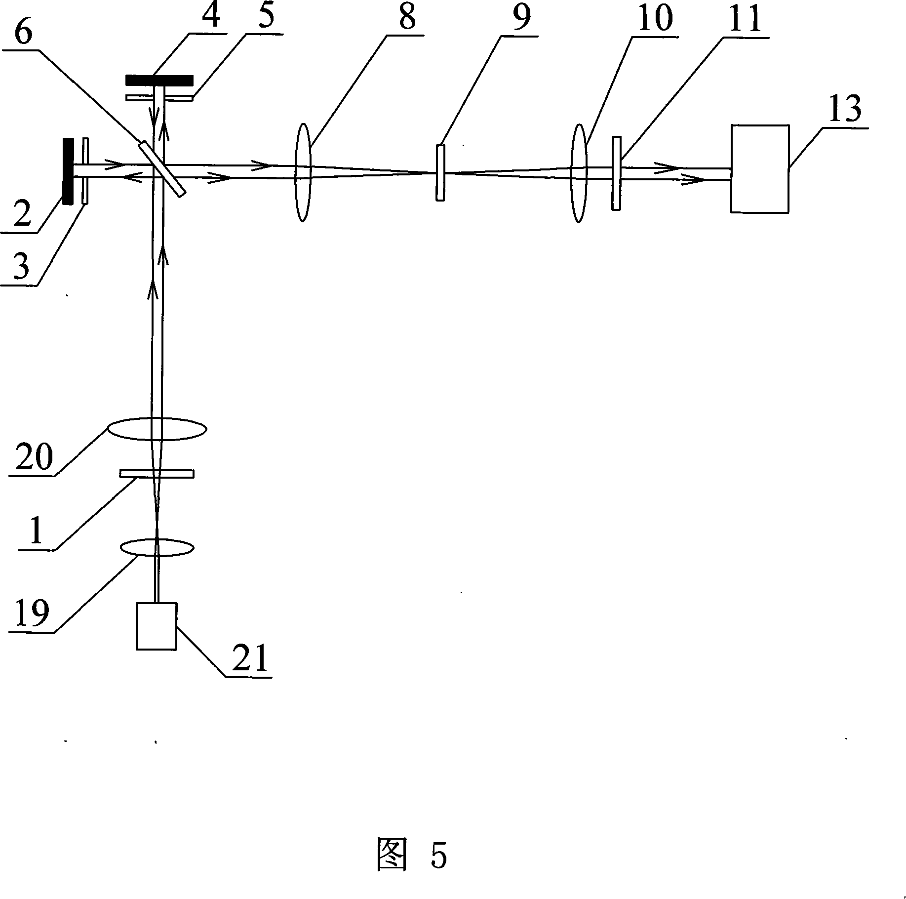
[0023] Specific embodiment two: Referring to Fig. 5, this embodiment increases the third convex lens 19 and the fourth convex lens 20 on the basis of specific embodiment one, the third convex lens 19, the first linear attenuation sheet 1 and the fourth convex lens 20 are all sequentially Be arranged on the optical path between the laser 21 and the first beam splitter 6, the optical axis of the transmitted light of the third convex lens 19 and the optical axis of the transmitted light of the fourth convex lens 20 are all aligned with the central axis of the laser emission port of the laser 21 Coincidentally, the focal length of the third convex lens 19 is smaller than the focal length of the fourth convex lens 20 . The 3rd convex lens 19 and the 4th convex lens 20 form the beam expander system, make a focus of the 3rd convex lens 19 and a focus of the 4th convex lens 20 coincide between them, the beam expander system can make the laser beam collimated and expanded that the laser...

specific Embodiment approach 3

[0024] Specific embodiment three: Referring to Fig. 6, this embodiment adds the second beam splitter 7, the third beam splitter 12, the fifth convex lens 14, the third total reflection mirror 15 and the fourth total reflection on the basis of the specific embodiment one mirror 18, the second beamsplitter 7 is arranged on the optical path between the first beamsplitter 6 and the first convex lens 8, the third beamsplitter 12 is arranged on the optical path between the second linear attenuation sheet 11 and the CCD camera 13, the second beamsplitter Two beam splitters 7 and the first beam splitter 6 are arranged parallel to each other, the angle between the third beam splitter 12 and the second beam splitter 7 is 90 °, and the third total reflection mirror 15 is arranged on the reflected light of the second beam splitter 7 On the optical path, the reflective surface of the third total reflection mirror 15 faces to the right side and forms an angle of 45° with the central axis of ...


PUM


Abstract

The coherent imaging device of 4f position based on the Michelson's interferometer is the third-order nonlinear refractive index used to measure the nonlinear photo medium. It can solves the problem of data treating bother, nonlinear absorption of traditional 4f coherent imaging technology and the small deform range, high request for stability and complex data treating of Mach-Zehnder interference. The first linear attenuating sheet, the first beam splitter, the second aperture diaphragm and second all-mirror are set at the central axis of the laser emitting mouth. the right side of low emitting point on first beam splitter is 45degree with the central axis of laser emitting mouth. The second linear attenuating sheet, the second convex, the first convex, the first beam splitter, the first aperture diaphragm and the first all-mirror are set at the central axis of the CCD camera image collecting side; the lower side of right emitting point on first beam splitter is 45degree with the central axis of image collecting side.

Description

technical field [0001] The invention relates to a device for measuring the third-order nonlinear refractive index of a nonlinear photonics medium, belonging to the fields of nonlinear photonics materials and nonlinear optical information processing. Background technique [0002] With the rapid development of optical communication and optical information processing and other fields, the research of nonlinear optical materials is becoming more and more important. The realization of functions such as optical switching, phase complex conjugation, optical limiting, and optical modulation mainly depends on the research progress of nonlinear optical materials, and optical nonlinear measurement technology is one of the key technologies for studying nonlinear photonic materials. At present, the commonly used methods for measuring nonlinear optical parameters include Z-scan, 4f system coherent imaging technology, Mach-Zehnder interferometry, four-wave mixing, third-harmonic nonlinear ...

Claims


Application Information

Patent Timeline
IPC IPC(8): G01N21/45G06F19/00
Inventor 潘广飞李云波杨昆宋瑛林王玉晓张学如
Owner HARBIN INST OF TECH
Why Eureka
Try Eureka