Transmission line lightning stroke on-line monitoring system

A technology for monitoring systems and transmission lines, applied in signal transmission systems, electrical signal transmission systems, measuring devices, etc., can solve problems such as large initial investment, impact on measurement accuracy, and saturation of strong lightning currents, and achieve automatic operation, automatic operation, and data Accurate and stable detection results

Active Publication Date: 2008-03-26
STATE GRID HUBEI ELECTRIC POWER RES INST +1
View PDF0 Cites 43 Cited by
  • Summary
  • Abstract
  • Description
  • Claims
  • Application Information

AI Technical Summary

Problems solved by technology

Its main disadvantages are: the formula and production process of the magnetic steel rod are dispersed, and the exact relationship between the residual magnetism on the magnetic steel rod and the measured lightning current cannot be determined uniformly; the residual magnetism of the magnetic steel rod with recorded lightning current information is easy to be transported The process is changed due to vibration, resulting in the loss of "information"; the magnetic steel rod cannot measure the lightning current below several thousand amps, and sometimes it will be saturated due to the strong lightning current; the magnetic field of the measurement environment also affects the measurement accuracy, and the error analysis shows that the largest The error can reach more than 100%
[0007] (1) The equipment is complicated and the initial investment is large;
[0008] (2) The positioning system itself has certain errors and detection dead zones;
[0009] (3) Terrain factors have great interference to the detection station, and the error is large;
[0010] (4) Cannot accurately locate the tower struck by lightning;
[0011] (5) There is an error in the calculation of the lightning current amplitude by the positioning system, which cannot be actually checked at present;
[0012] (6) The lightning current waveform cannot be given
No online lightning strike monitoring system or device for transmission lines has been disclosed or used after searching

Method used


Image

  • Transmission line lightning stroke on-line monitoring system
  • Transmission line lightning stroke on-line monitoring system
  • Transmission line lightning stroke on-line monitoring system

Examples


Embodiment Construction

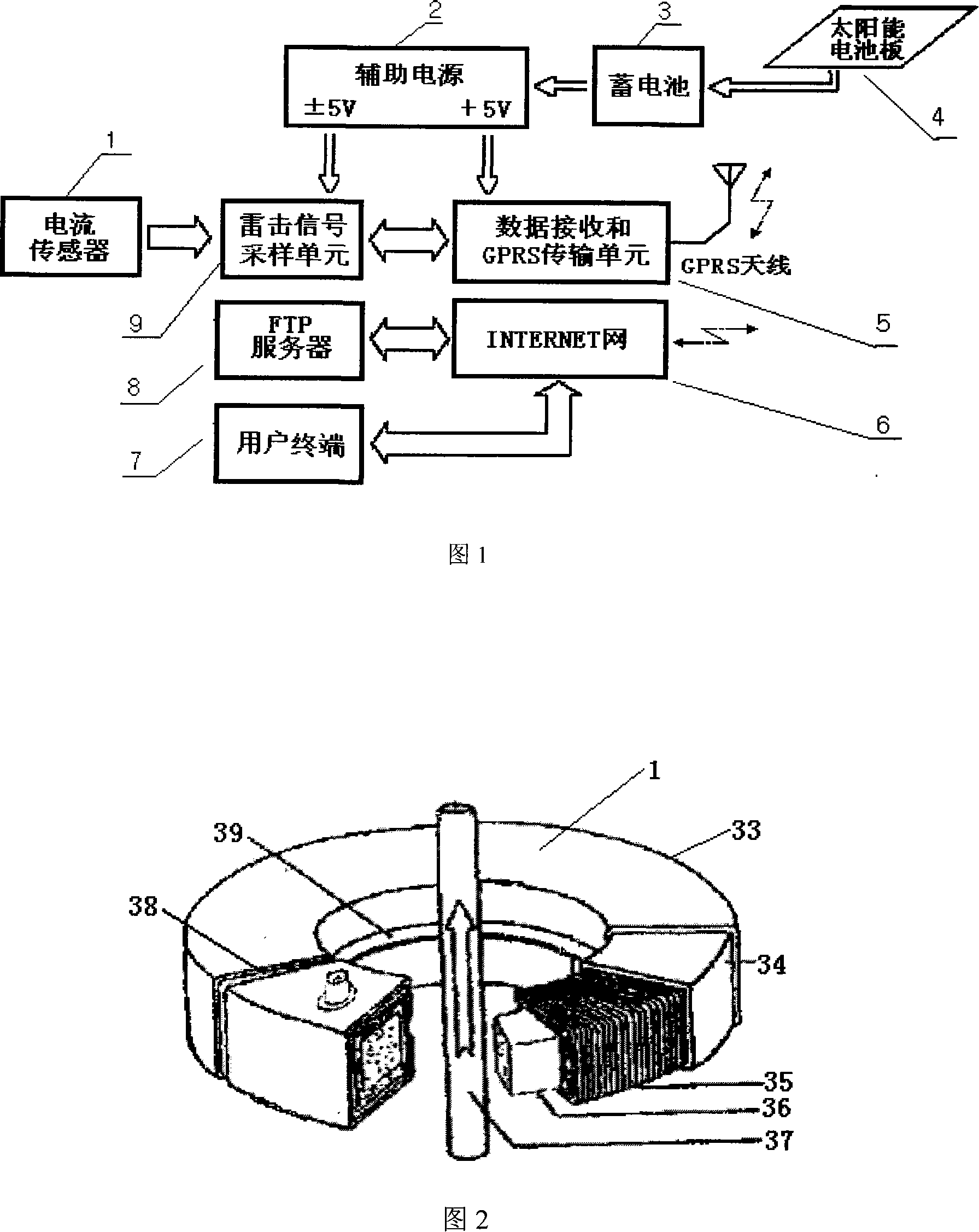
[0041] Figure 1 shows the structural block diagram of the online lightning strike monitoring system for transmission lines, and its connection relationship and functions are as follows.

[0042] The storage battery 3 is connected to the solar panel 4 and the voltage converter (auxiliary power supply) 2 respectively, and the direct current converted from sunlight by the solar panel 4 is sent to the storage battery 3 by two wires, and at the same time connected to the DC / DC conversion module—voltage converter (auxiliary power supply) 2, the battery 3 voltage is converted into the voltage required by the weak part of the monitoring system; the voltage converter 2 is connected with the lightning signal sampling unit 9, data receiving and GPRS transmission unit 5 respectively, and the lightning signal sampling unit 9 is connected with Current sensor 1, data reception and GPRS transmission unit 5 are connected, and this group of voltage is connected to lightning strike signal samplin...


PUM


Abstract

This invention discloses a kind of transmit electricity circuit lightning strike online monitor system, it includes the current sensor, the lighting strike signal collection cell, the Russell loop, the accumulator links with the solar battery, the pressure converter separately, the pressure converter links with the lighting strike signal collection cell, data receive and GPRS transmission cell separately, the lighting strike signal collection cell links with the current sensor, data receive and GPRS transmission cell separately, the lighting strike signal collection cell A / D sends the gained thunderstorm current data to the data receive and GPRS transmission cell through the RS232 interface after collecting, the data receive and GPRS transmission cell sends the data gained by each thunderstorm current sensor to the internet by handset network, then to the FTP server, links with the user terminal by the server use network line. The structure of this invention is simple, the operation is automatic, the measurement is stable, the data is correct.

Description

technical field [0001] The invention relates to the field of lightning protection for electrical equipment in a power system, in particular to an online lightning strike monitoring system for an overhead power transmission line. It is suitable for judging the form of lightning strikes on overhead transmission lines and measuring lightning current parameters and waveforms. Background technique [0002] So far, the relevant research achievements at home and abroad mainly include the following types. [0003] 1 Magnetic steel rod method [0004] The earliest foreign instrument successfully developed for measuring the maximum magnitude of lightning current was made by Komel-Kov and Stekoinikov in 1941 with a loop antenna and a magnetic steel rod, and it is still used in power systems. Its main disadvantages are: the formula and production process of the magnetic steel rod are dispersed, and the exact relationship between the residual magnetism on the magnetic steel rod and the...

Claims


Application Information

Patent Timeline
Patent Type & Authority Applications(China)
IPC IPC(8): G01R19/00G01R19/04G01R19/175G01R19/14G08C17/02G08C19/00H04M11/00
Inventor 汪涛周文俊
Owner STATE GRID HUBEI ELECTRIC POWER RES INST
Why Eureka
Try Eureka