Giant magnetoresistance sensor characteristic detection device and method

A giant magnetoresistance and detection device technology, applied in the direction of measuring devices, instruments, and measuring electrical variables, can solve the problems of lack of giant magnetoresistance sensors, high cost of current sources, and lack of simple and feasible means for performance testing, etc., to achieve equipment The effect of simple structure and convenient operation

Inactive Publication Date: 2008-03-26
BEIHANG UNIV
View PDF0 Cites 15 Cited by
  • Summary
  • Abstract
  • Description
  • Claims
  • Application Information

AI Technical Summary

Problems solved by technology

The magnetic field generated by the permanent magnet is a static magnetic field. The frequency of the solenoid magnetic field depends on the current passing through the solenoid, and the current source with continuously changing frequency and amplitude is expensive.
In this way, although the frequency band of the giant magnetoresistance sensor is very wide, the existing test system is basically a test at a certain frequency point, lacking the means of comprehensively testing the performance of the giant magnetoresistance sensor in a wider frequency band, and developing a new magnetic field generating device imminent
[0003] In addition, the existing giant magnetoresistance sensor testing system lacks simple and feasible means for testing the performance under temperature and vibration interference. Temperature testing usually requires the cooperation of a temperature control box, and vibration testing requires the intervention of a shaking table. At the same time, it also increases the complexity of system design, implementation and tuning
The application of giant magnetoresistive sensors will encounter the influence of factors such as temperature and vibration. The current test system lacks a comprehensive test and evaluation of sensor performance under the comprehensive effects of multiple factors.
[0004] In addition, the existing test systems generally have complex structures, and the operation is not simple and convenient enough, so it is difficult to meet the comprehensive and rapid test of the characteristics of giant magnetoresistive sensors in large quantities.

Method used


Image

  • Giant magnetoresistance sensor characteristic detection device and method
  • Giant magnetoresistance sensor characteristic detection device and method

Examples


Embodiment Construction

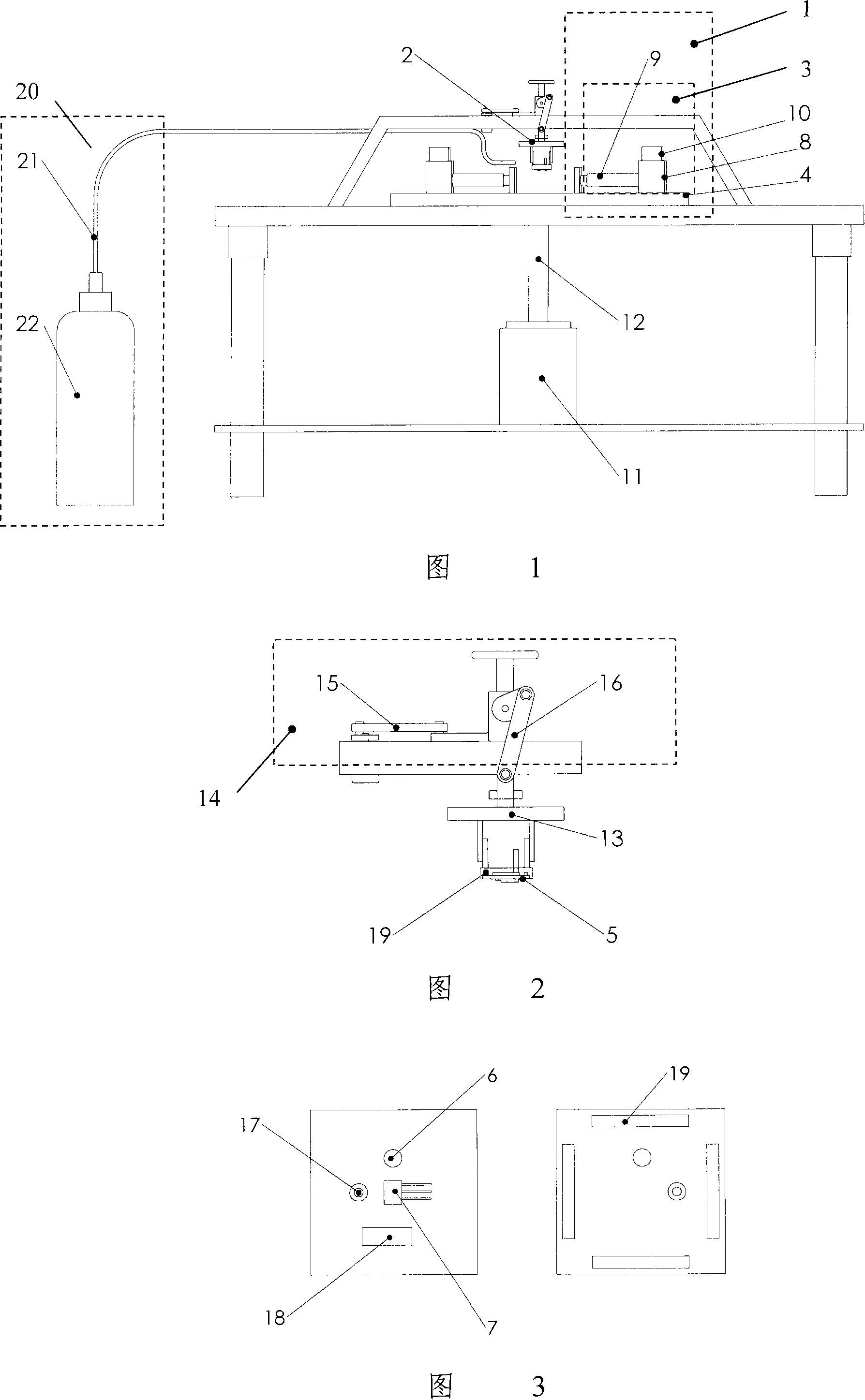
[0024] As shown in Figure 1, it is a giant magnetoresistance sensor characteristic detection device. The system consists of a magnetic field generator 1 and a giant magnetoresistance sensor placement device 2. The magnetic field generator 1 is used to generate continuous changes by changing the position of the magnet and the rotational speed of the motor. Alternating magnetic field; the giant magnetoresistance sensor placement device 2 is used to output a voltage signal to measure the alternating magnetic field. The magnetic field generating device 1 is composed of a magnet position adjustment mechanism 3 and a rotating platform 4. The magnet position adjustment mechanism 3 is used to generate a continuously changing static magnetic field by changing the position of the magnet; the rotating platform 4 is used to generate an alternating magnetic field by changing the motor speed. The magnet position adjustment mechanism 3 is fixed on the rotating platform 4, the rotating platfor...


PUM


Abstract

The invention relates to a characteristic detecting facility through gigantic magnetic resistance (GMR) feeler search. This invention is consist of magnetic field arisesing device, which include magnet position modulating parts and a revolution flat roof, and gigantic magnetic resistance (GMR) feeler search depositing device which located in the central of the magnetic field arisesing device. The invention disclosed a characteristic gigantic magnetic resistance (GMR) feeler search detecting method. In broad-band magnetic field, it can work well under the temperature and libration interferes. Due to this reason, the capability changing of a feeler search under such interfere is overall evaluated, then, an input-output characteristic curve will be built in nature. This facility is simple and convinence, especially proper for quick gigantic magnetic resistance (GMR) feeler search characteristic detecting in large quantities.

Description

technical field [0001] The invention relates to giant magnetoresistance (GMR) sensor detection technology, in particular to a giant magnetoresistance sensor characteristic detection device and method under the action of a wider frequency band magnetic field. Background technique [0002] Existing giant magnetoresistance sensor test systems are all composed of magnetic field generators and sensor automatic test systems. The magnetic field generating device is composed of permanent magnets or solenoids, etc., and the automatic test system is mostly based on LabVIEW software. The magnetic field generated by the permanent magnet is a static magnetic field, the frequency of the magnetic field of the solenoid depends on the current passing through the solenoid, and the current source with continuously changing frequency and amplitude is expensive. In this way, although the frequency band of the giant magnetoresistance sensor is very wide, the existing test system is basically a t...

Claims


Application Information

Patent Timeline
Patent Type & Authority Applications(China)
IPC IPC(8): G01R35/00G01R33/09
Inventor 钱政陈从强任雪蕊
Owner BEIHANG UNIV
Why Eureka
Try Eureka