
A disposable blood plasma separation bag

A plasma separation, disposable technology, applied in the field of plasma separation bags, can solve the problems of long separation time, complex separation structure, and complicated separation methods, and achieve the effects of ensuring good health, simple and compact structure, and shortening separation time.

Inactive Publication Date: 2008-04-09
翟周宣
View PDF2 Cites 2 Cited by
  • Summary
  • Abstract
  • Description
  • Claims
  • Application Information

AI Technical Summary

Problems solved by technology

This separation method is complicated and takes a long time to collect. In addition, human blood components are arranged according to their specific gravity, which are red blood cells, white blood cells, lymphocytes, platelets and plasma. Medically, only the components they need will be given to patients according to their needs, such as , it is only necessary to separate the plasma and infuse it to the patient, and reinfuse the rest to the blood donor. This is more scientific and reasonable. It not only takes care of the needs of the patient, but also ensures the health of the blood donor to the greatest extent. It is a great source of blood medicine. saving
However, unfortunately, this solution has not been adopted in the prior art. For example, in Chinese patents 200420082755.2 and 200420039692.2, the problem of one-time separation of useful substances is not solved, the separation structure is complex, and the time required for separation is long

Method used

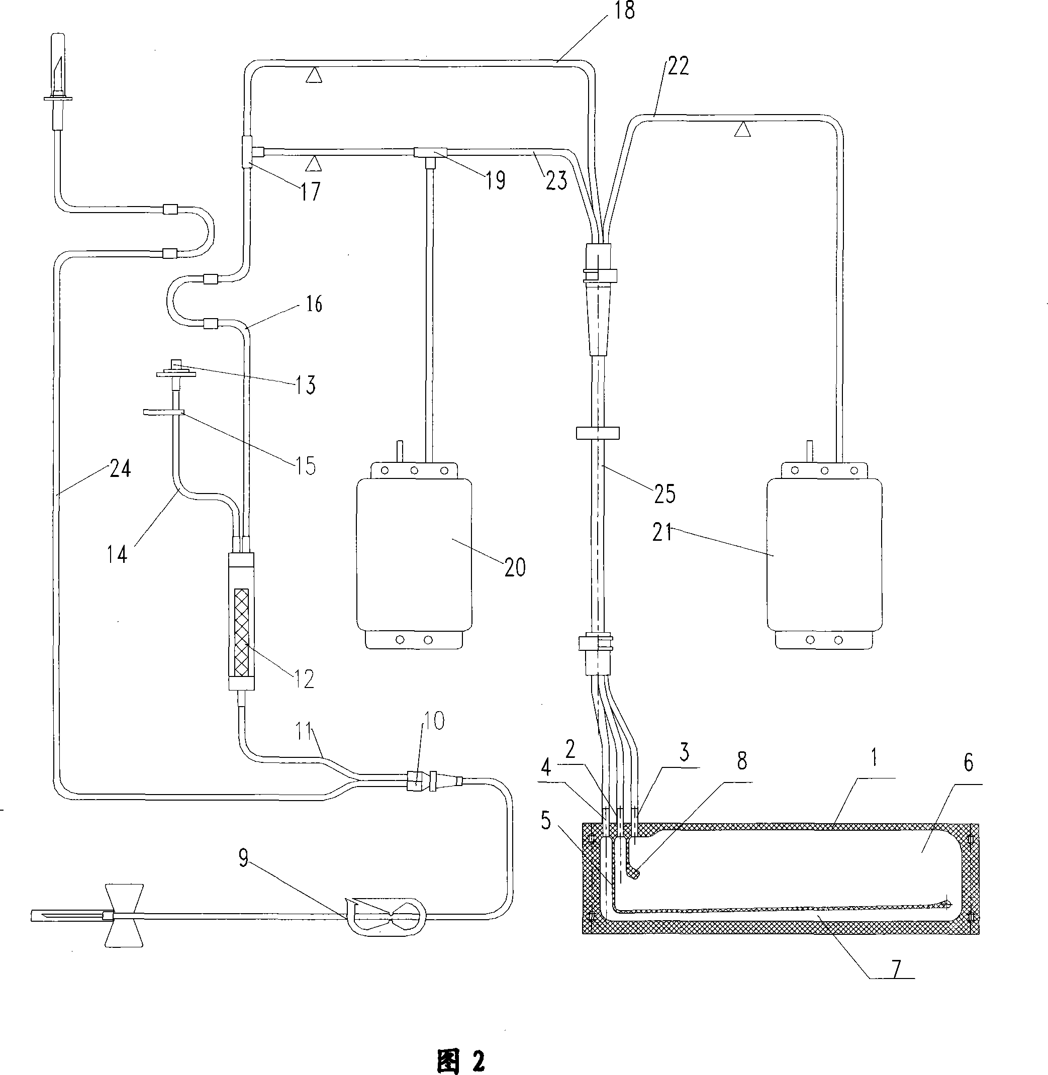

Image

  • A disposable blood plasma separation bag
  • A disposable blood plasma separation bag

Examples


Embodiment Construction

[0013] Below in conjunction with accompanying drawing and embodiment the present invention will be further described:

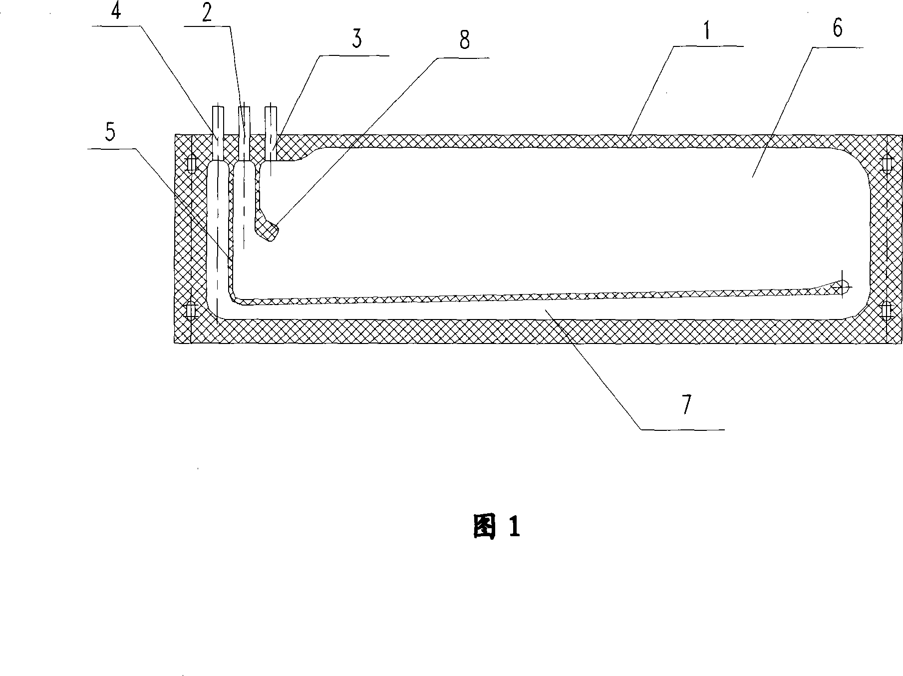
[0014] It can be seen from Figure 1 that the disposable plasma separation bag includes a closed bag body 1, a whole blood inlet 2, a poor component plasma outlet 3, and a rich component plasma outlet 4, and an "L"-shaped thermal synthesis isolation line passes through the bag body. 5 Divide the inner space of the bag body into upper and lower cavities 6 and 7, one end of the upper cavity 6 and the lower cavity 7 are connected, and the other end is isolated, and the component-rich plasma outlet 4 is located at the end of the lower cavity 7, that is, the component-rich The last end of the plasma flow path, the whole blood inlet 2 and the poor component plasma outlet 3 are located at the upper end of the upper cavity 6 .

[0015] In order to improve the separation effect, as an improvement of the present invention, a guide block 8 is also provided between the wh...


PUM


Abstract

The invention discloses a plasma separating bag which is matched with a blood separating machine to be used, and the plasma separating bag is mainly used to separate components from the blood of a blood donor; the invention comprises an airlocked bag body, a whole blood inlet opening, a poor component plasma outlet opening and a rich component plasma outlet opening. The internal space of the bag body is divided into an upper cavity and a lower cavity through an L-shaped thermal synthesis separation line in the bag body, the upper cavity and the lower cavity are integrally communicated, the other ends of the upper cavity and the lower cavity are insolated, the rich component plasma outlet opening is positioned on the end part of the lower cavity, namely, the tail end of a rich component plasma flow route, the whole blood inlet opening and the poor component plasma outlet opening are positioned at the upper end of the upper cavity, the internal space of the bag body is divided into the upper cavity and the lower cavity through the L-shaped thermal synthesis separation line in the bag body, the separating structure can well and effectively separate the poor component plasma and the rich component plasma, and the structure is simpler and more compact; in addition, the invention changes the original two time separation way to lead the once separation of the blood to be accomplished and to greatly reduce the separating time.

Description

technical field [0001] The invention relates to a disposable medical consumable device, in particular to a plasma separation bag matched with a blood separator, which is mainly used for separating plasma components from the blood of a blood donor. Background technique [0002] At present, the traditional method of collecting plasma is to use a separation cup. The plasma separation bag used with the blood separator is generally composed of a separation bag and a collection bag. The separation bag includes a bag body, a whole blood inlet, and a relatively dense The plasma component (rich component) outlet and the less dense plasma component (poor component) outlet are to centrifuge the blood in the separation bag to separate the denser components, mainly red blood cells, and then collect these heavy components into the collection bag In the process, the second centrifugation is performed, and the poor plasma with lower density separated again exits the collection bag and merge...

Claims


Application Information

Patent Timeline
IPC IPC(8): A61M1/38A61J1/10G01N1/10
Inventor 翟周宣
Owner 翟周宣
Learn More