Method for manufacturing ultra-hard composite blade
A technology of compound blades and manufacturing methods, which is applied in the direction of manufacturing tools, accessories of tool holders, and tools used in lathes, etc., can solve the problems of easy falling off and high production costs of superhard tools, and achieve increased strength, reduced production costs, and reduced The effect of dosage
- Summary
- Abstract
- Description
- Claims
- Application Information
AI Technical Summary
Problems solved by technology
Method used
Image
Examples
Embodiment 1
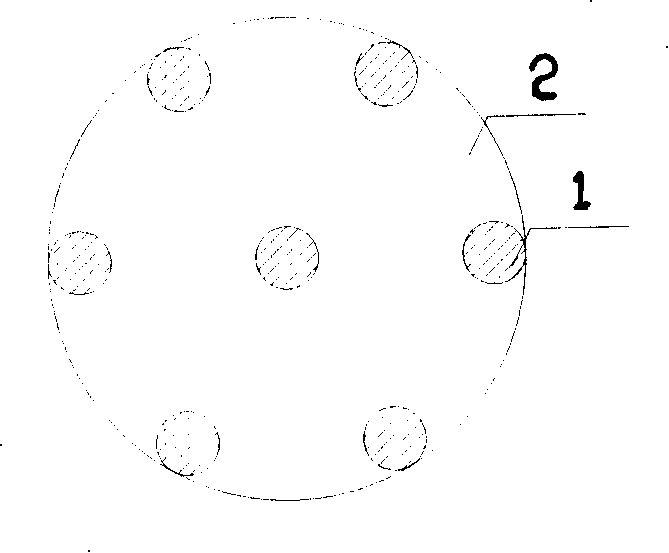
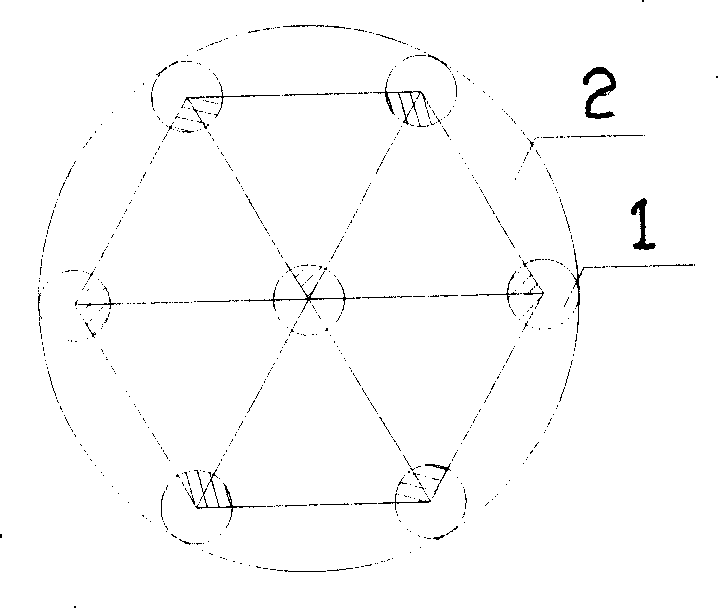
[0012] The manufacturing method of the present invention is as follows: firstly, the hard alloy or the high-speed steel plate (2) prepared as the blade base are drilled into the preformed hole to form the preformed hole (1), and then directly to the preformed hole under the protection of the sintering mould. (1) Add superhard material and binder powder into it, and convert the superhard material and binder powder in the preformed hole into superhard polycrystalline material after high temperature and high pressure sintering; the size and spacing of the preformed hole (1) should be based on Determine the shape and size of the blade to be produced, and then cut along the center of the preformed hole (1) to make the required blade specification. After the above cutting, the original superhard polycrystalline material in the preformed hole becomes the tip of the blade. The hard alloy or high-speed steel plate between the preformed holes (1) is the base of the blade, and then underg...
Embodiment 2
[0014] The manufacturing method of the present invention is as follows: firstly, the hard alloy or the high-speed steel plate (2) prepared as the blade base are drilled into the preformed hole to form the preformed hole (1), and then directly to the preformed hole under the protection of the sintering mould. (1) Add superhard material and binder powder into it, and convert the superhard material and binder powder in the preformed hole into superhard polycrystalline material after high temperature and high pressure sintering; the size and spacing of the preformed hole (1) should be based on Determine the shape and size of the blade to be produced, and then cut along the center of the preformed hole (1) to make the required blade specification. After the above cutting, the original superhard polycrystalline material in the preformed hole becomes the tip of the blade. The cemented carbide or high-speed steel plate between the preformed holes (1) is the base of the blade, and then ...
Embodiment 3
[0016] The manufacturing method of the present invention is as follows: firstly, the hard alloy or the high-speed steel plate (2) prepared as the blade base are drilled into the preformed hole to form the preformed hole (1), and then directly to the preformed hole under the protection of the sintering mould. (1) Add superhard material and binder powder into it, and convert the superhard material and binder powder in the preformed hole into superhard polycrystalline material after high temperature and high pressure sintering; the size and spacing of the preformed hole (1) should be based on Determine the shape and size of the blade to be produced, and then cut along the center of the preformed hole (1) to make the required blade specification. After the above cutting, the original superhard polycrystalline material in the preformed hole becomes the tip of the blade. The cemented carbide or high-speed steel plate between the preformed holes (1) is the base of the blade, and then ...
PUM
| Property | Measurement | Unit |
|---|---|---|
| Thickness | aaaaa | aaaaa |
Abstract
Description
Claims
Application Information
 - R&D
- Intellectual Property
- Life Sciences
- Materials
- Tech Scout
- Unparalleled Data Quality
- Higher Quality Content
- 60% Fewer Hallucinations
Browse by: Latest US Patents, China's latest patents, Technical Efficacy Thesaurus, Application Domain, Technology Topic, Popular Technical Reports.
© 2025 PatSnap. All rights reserved.Legal|Privacy policy|Modern Slavery Act Transparency Statement|Sitemap|About US| Contact US: help@patsnap.com


