Method for increasing nitrogen content of nitrogen-containing clean steel

A pure steel and molten steel technology, applied in the field of nitrogen addition of alloy steel in the metallurgical industry, can solve the problems of poor purity of molten steel, poor nitrogen absorption stability, large fluctuations in nitrogen content, etc., to achieve cost reduction, low production cost, and easy The effect of control

Inactive Publication Date: 2010-10-13
BAOSTEEL SPECIAL STEEL CO LTD
View PDF4 Cites 2 Cited by
  • Summary
  • Abstract
  • Description
  • Claims
  • Application Information

AI Technical Summary

Problems solved by technology

[0004] In the prior art, there are two ways to increase nitrogen in alloy steel: (1) one is to add solid nitrogen-containing alloy: in the later stage of refining in the steelmaking process, valuable solid nitrogen-containing alloy is added to liquid steel, and nitrogen-containing alloy The nitrogen element in the molten steel is absorbed by the molten steel, so that the molten steel reaches a certain nitrogen content; the disadvantage of this nitrogen increase method is that the cost of steel smelting is high, and the nitrogen absorption stability of the steel is poor, which easily leads to the nitrogen content in the molten steel Large fluctuations, even the composition of nitrogen exceeds the standard range
(2) Another way is to blow nitrogen gas into the molten steel, and part of the nitrogen element in the nitrogen gas is absorbed by the molten steel, so that the molten steel reaches a certain nitrogen content; There is a certain solubility in nitrogen, the price of nitrogen is relatively cheap, and the smelting cost is low; the disadvantage is: after blowing nitrogen, the purity of molten steel is poor, which does not meet the requirements of pure steel

Method used


Image

  • Method for increasing nitrogen content of nitrogen-containing clean steel
  • Method for increasing nitrogen content of nitrogen-containing clean steel
  • Method for increasing nitrogen content of nitrogen-containing clean steel

Examples


Embodiment 1

[0031] After the nitrogen-containing steel is treated in a 100t electric furnace, refined in a 100t ladle furnace and VD vacuum degassing treatment, the nitrogen in the molten steel is 0.012% (the standard nitrogen requirement is 0.03% to 0.06%, and the target is 0.045%), and other chemical components are all qualified.

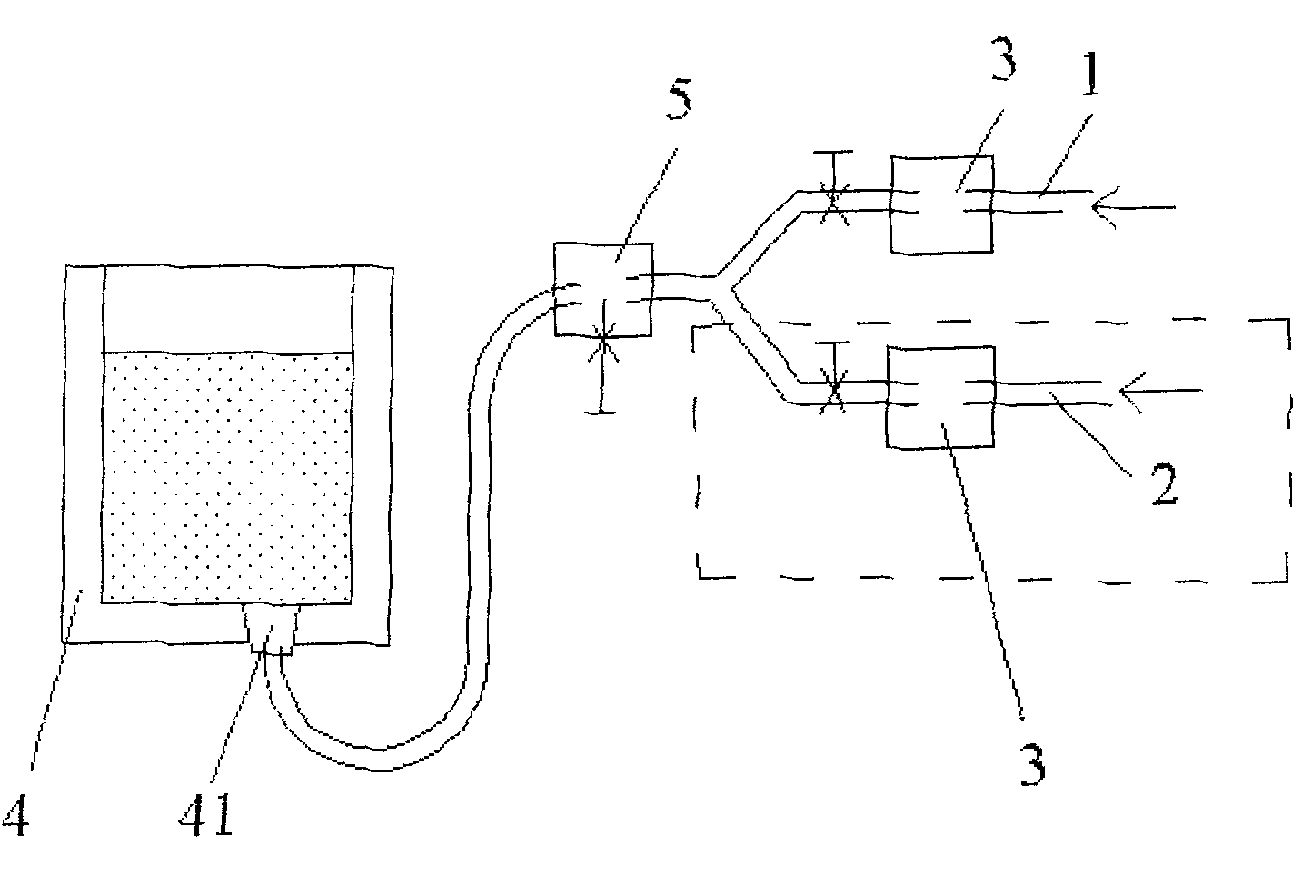
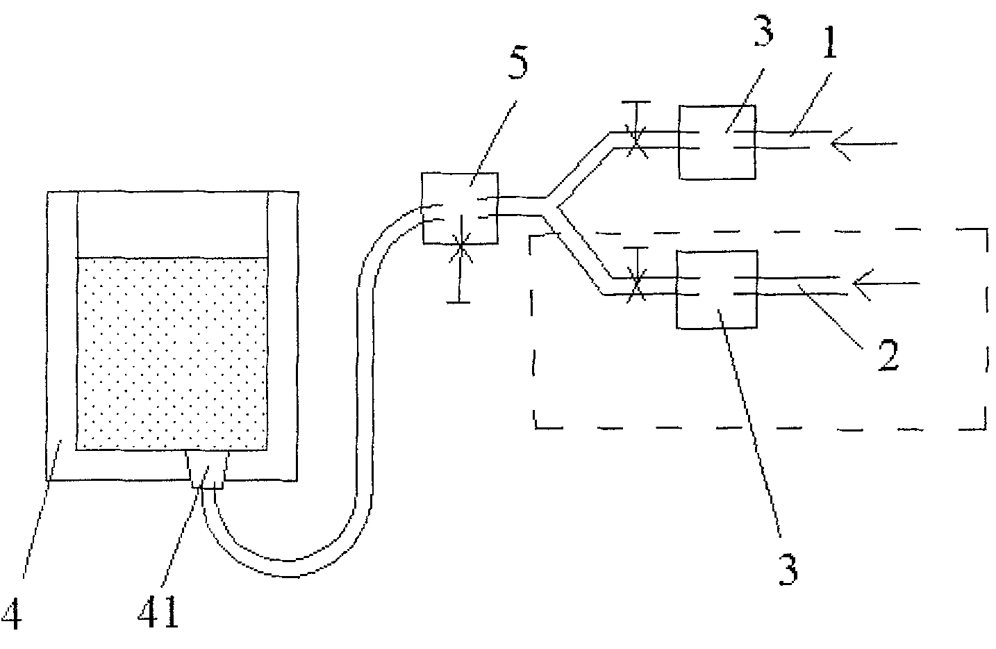
[0032] As shown in Figure 1, the ladle bottom blowing system is a pipeline system equipped with two sub-pipelines. On the original ladle single-circuit system, a nitrogen blowing pipeline is added to form two sub-pipelines, namely argon sub-pipeline 1 and nitrogen sub-pipeline Road 2, and merged into a pipeline system of the main pipeline. On-off valves and pressure gauges 3 are arranged in the sub-pipelines, and a pressure-reducing valve 5 is arranged on the main pipeline connected to the air-permeable brick 41 at the bottom of the ladle 4 .

[0033] Check the original gas pressure, pure argon: pressure 0.5MPa, purity 99.99%; industrial nitrogen: pressure 0....

Embodiment 2

[0040] After the nitrogen-containing steel is treated in a 100t electric furnace, refined in a 100t ladle furnace, and VD vacuum degassed, the nitrogen in the molten steel is measured to be 0.015% (standard nitrogen requirements are 0.03% to 0.06%, and the target is 0.040%), and other chemical components have been tested. qualified.

[0041] Still use the pipeline system with two sub-pipelines as shown in Figure 1, one pipeline for blowing nitrogen and one pipeline for blowing argon, check the original pressure of the gas, pure argon: the pressure is 0.4MPa, the purity is 99.99%; industrial nitrogen: the pressure is 0.4 MPa, purity 99.5%.

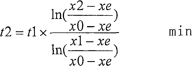
[0042] The first step is to turn off the argon, analyze the nitrogen content x0=0.015%, start blowing nitrogen, and control the pressure of nitrogen blown into the ladle through the pressure reducing valve to 0.45Mpa. Check the metallurgical manual, and the xe of this component steel is 0.2143% (xe is steel The equilibrium solubility can b...

Embodiment 3

[0048] After the nitrogen-containing steel is treated in a 60t electric furnace, refined in a 60t ladle furnace and VD vacuum degassing treatment, the measured nitrogen in the molten steel is 0.014% (standard nitrogen requirement is 0.03% to 0.06%, and the target is 0.045%), and other chemical components have been tested. qualified.

[0049] Still use the pipeline system with two sub-pipelines as shown in Figure 1, one pipeline for blowing nitrogen, one pipeline for blowing argon, check the original pressure of the gas, pure argon: the pressure is 0.3MPa, the purity is 99.99%; industrial nitrogen: the pressure is 1.0 MPa, purity 99.5%.

[0050] The first step is to turn off the argon gas, analyze the nitrogen content x0=0.014%, start blowing nitrogen gas, and control the pressure of nitrogen gas blown into the ladle to 0.50MPa through the pressure reducing valve. Check the metallurgical manual, and the xe of this component steel type is 0.2259% (xe is steel The equilibrium so...


PUM


Abstract

The invention relates to a nitrogen increasing method for nitrogen-bearing pure steel. The invention comprises the following steps: nitrogen increasing is performed to the melted steel in a steel ladle at the final stage of the second refining of nitrogen-bearing pure steel by adopting the method of nitrogen gas blowing to a steel ladle bottom; after nitrogen blowing, argon gas is blown to the melted steel immediately, to clean the melted steel. The nitrogen gas and the argon gas are respectively conveyed to the steel ladle bottom through two pipes. Through the cleaning argon gas after nitrogen gas is blown, the invention enables the foreign impurities in the melted steel to be removed to produce pure steel material, and the method can increase the nitrogen content of the melted steel at low cost, and simultaneously satisfy the request of the melted steel of the pure alloy steel to the purity thereof.

Description

technical field [0001] The invention relates to a nitrogen-increasing method for alloy steel in the metallurgical industry, in particular to a nitrogen-increasing method for nitrogen-containing pure steel. Background technique [0002] According to the content of harmful impurity elements or harmful gases in steel, alloy steel can be divided into ordinary alloy steel and pure alloy steel (hereinafter referred to as pure steel). Compared with the smelting process of ordinary alloy steel, pure steel smelting requires class B inclusions ≤ 1.5, class C inclusions = 0, and the requirements for smelting are very high. [0003] According to the usage characteristics of steel, certain nitrogen content is required in some steels. For example: in duplex stainless steel, N as an austenite phase forming element plays an important role: during rapid cooling of the heat-affected zone of the welded joint, N promotes the reversal of ferrite formed at high temperature into sufficient second...

Claims


Application Information

Patent Timeline
Patent Type & Authority Patents(China)
IPC IPC(8): C21C7/00C22C33/04
Inventor 林俊廖俊刘军占陈锡民陈晓文
Owner BAOSTEEL SPECIAL STEEL CO LTD
Why Eureka
Try Eureka