Large depth underground continuous wall water-stop joint device

An underground diaphragm wall and joint device technology, applied in water conservancy projects, underwater structures, artificial islands, etc., can solve problems such as failure to bury the waterstop, difficult to dismantle as a whole, loss of waterproofing, etc., and achieve reform of construction technology, installation and dismantling. Simplify and avoid the effect of mud skin generation

Active Publication Date: 2008-04-30
SHANGHAI URBAN CONSTRUCTION MUNICIPAL ENGINEERING (GROUP) CO LTD
View PDF1 Cites 20 Cited by
  • Summary
  • Abstract
  • Description
  • Claims
  • Application Information

AI Technical Summary

Problems solved by technology

However, its deficiencies or defects are also fully revealed in engineering practice
[0009] On the one hand, because the cross-section of the waterproof joint plate is roughly two trapezoidal combinations arranged up and down, it is difficult to dismantle it as a whole in large-depth engineering construction
[0010] On the other hand, because the two ends and the middle part of the cross-section of the rubber waterstop are circular, its anchoring force in the concrete is small, and it may be pulled out of the concrete if it is accidentally operated during the demoulding operation , causing the waterstop to fail to bury and lose the effect of waterproofing
[0011] Therefore, there is the limitation of engineering construction depth in above-mentioned this waterproof joint device

Method used


Image

  • Large depth underground continuous wall water-stop joint device
  • Large depth underground continuous wall water-stop joint device
  • Large depth underground continuous wall water-stop joint device

Examples


Embodiment Construction

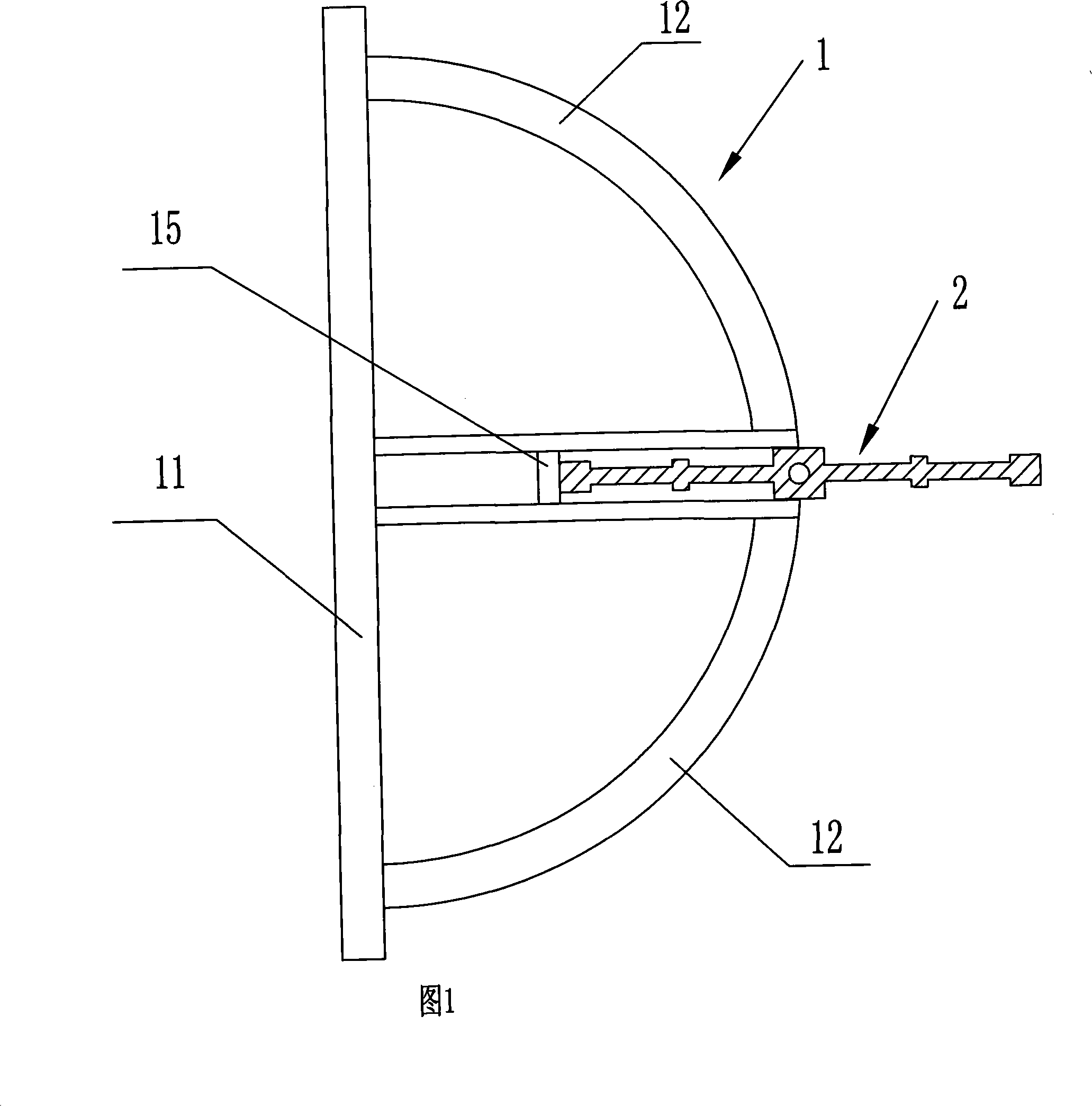
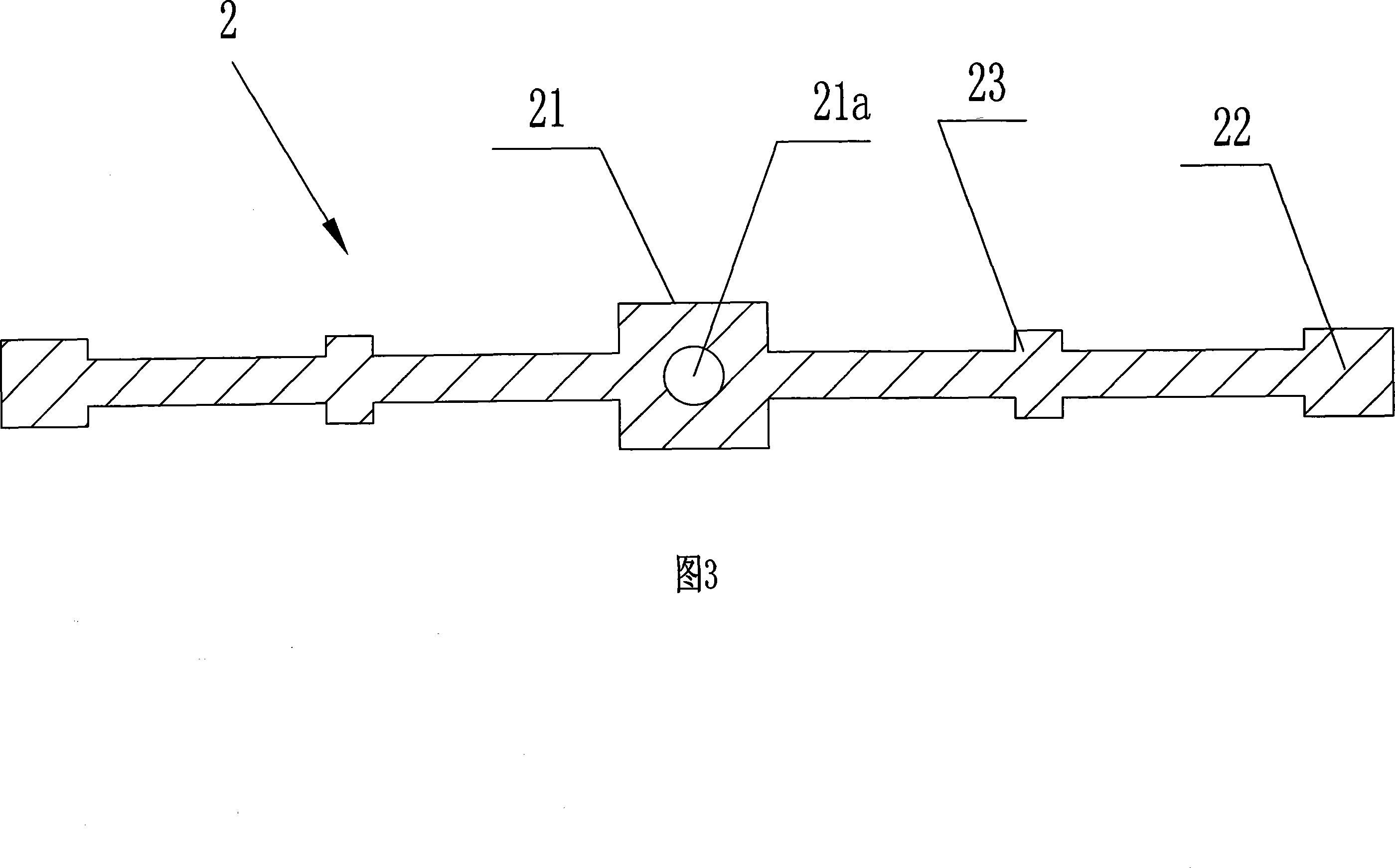
[0054] Referring to Figures 1, 2, and 3, and referring to Figures 4, 5, and 6 for cooperation, the water-stop joint device for a large-depth underground diaphragm wall of the present invention mainly includes a water-stop joint plate 1, and a rubber water-stop seal embedded in the water-stop joint plate 1 with 2.

[0055] 1. Waterproof joint plate

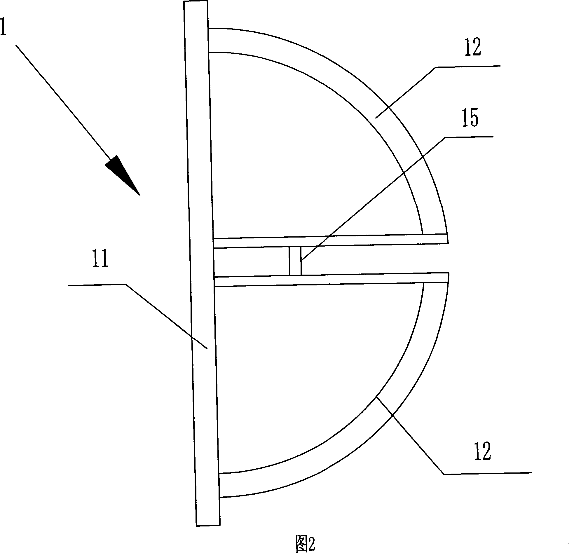
[0056] The water-stop joint plate 1 of the present invention is a steel structural member, including joint side plates 11, two arc-shaped plates 12, H-shaped groove plates 15, upper and lower end plates 13, 14, which are fixed and connected in sequence;

[0057] Two arc-shaped plates 12 are set opposite to each other along the plate width of the joint side plate 11; the H-shaped groove plate 15 is centrally arranged between the two arc-shaped plates 12; the two open ends of the H-shaped groove plate 15, the two ends of one end The outer sides are fixedly connected with two arc-shaped plates 12 respectively, and the two ends of the...


PUM


Abstract

The invention relates to a water sealing joint device of a large-depth underground continuous wall. The water sealing joint device consists of a water sealing connector plate and a rubber water stop; the water sealing connector plate comprises connector side plates connected in sequence, two arc shape plates, an H-shaped groove plate, an upper end plate and a lower end plate; the two arc shape plates are oppositely arranged in the middle at intervals along the width of a connector side plate, and the H-shaped groove plate is arranged in the middle between the two arc shape plates; the H-shaped groove plate has two opening ends, one end is fixed and connected with the two arc shape plates, and the other end is fixed and connected with the connector side plate; and the upper end plate and the lower end plate are arranged at the end parts of the two arc shape plates and the H-shaped groove plate. An opening slot is arranged at the middle part of the upper end plate and the lower end plate, and the rubber water stop is embedded in a gap between the opening slot and the opening end of the H-shaped groove plate. The connector side plate adopts a long strip shape thick steel plate, the upper end plate and the lower end plate adopt semi-circular steel plates, and the composite cross section of the two arc shape plates is matched with the shape of the upper end plate and the lower end plate. The depth of the opening slot of the upper end plate and the lower end plate is approximately identical to half of the width of the rubber water stop. The invention can improve the prior construction process, reduce the construction cost, and effectively improve the water sealing performance of the structure of the underground continuous wall.

Description

technical field [0001] The invention belongs to the technical field of underground diaphragm wall engineering construction, and relates to auxiliary equipment for underground diaphragm wall engineering construction, in particular to a large-depth underground diaphragm wall water-stop joint device. Background technique [0002] With the rapid development of my country's construction industry, underground diaphragm wall engineering technology has been widely used in the field of foundation engineering. The underground diaphragm wall is to use a special trenching equipment on the ground to excavate a long and narrow deep trench in the case of mud retaining wall, place a steel cage in the trench, pour concrete, and build a reinforced concrete wall section. These wall sections are connected one by one for water interception, seepage prevention, soil retaining or load bearing. [0003] This kind of wall body constructed by connecting sections is often the enclosure body for water...

Claims


Application Information

Patent Timeline
Patent Type & Authority Applications(China)
IPC IPC(8): E02D29/16E02D29/02
Inventor 邹奇鸣朱剑波储文奇刘德勇马留成
Owner SHANGHAI URBAN CONSTRUCTION MUNICIPAL ENGINEERING (GROUP) CO LTD
Why Eureka
Try Eureka