
Calibration device for aligning system of stepper and its calibration method

A technology of an alignment system and a calibration device, which is applied to the exposure device of photoengraving process, microlithography exposure device, image data processing, etc. Installation requirements, the difficulty of achieving a higher-precision alignment system, etc., to achieve the effect of improving accuracy, easy placement, and reducing calculation errors

Active Publication Date: 2008-04-30
SHANGHAI MICRO ELECTRONICS EQUIP (GRP) CO LTD
View PDF1 Cites 29 Cited by
  • Summary
  • Abstract
  • Description
  • Claims
  • Application Information

AI Technical Summary

Problems solved by technology

[0007] The purpose of the present invention is to provide a calibration device and calibration method that can be used for the alignment system of a stepper lithography machine, which can solve the algorithm defects of the alignment system in the current stepper lithography machine based on the perspective projection relationship, and the higher precision calibration. Barebone systems are difficult to implement, alignment accuracy and reliability are easily affected, and the calibration device does not meet the installation requirements of the stepper lithography machine.

Method used


Image

  • Calibration device for aligning system of stepper and its calibration method
  • Calibration device for aligning system of stepper and its calibration method
  • Calibration device for aligning system of stepper and its calibration method

Examples


Embodiment Construction

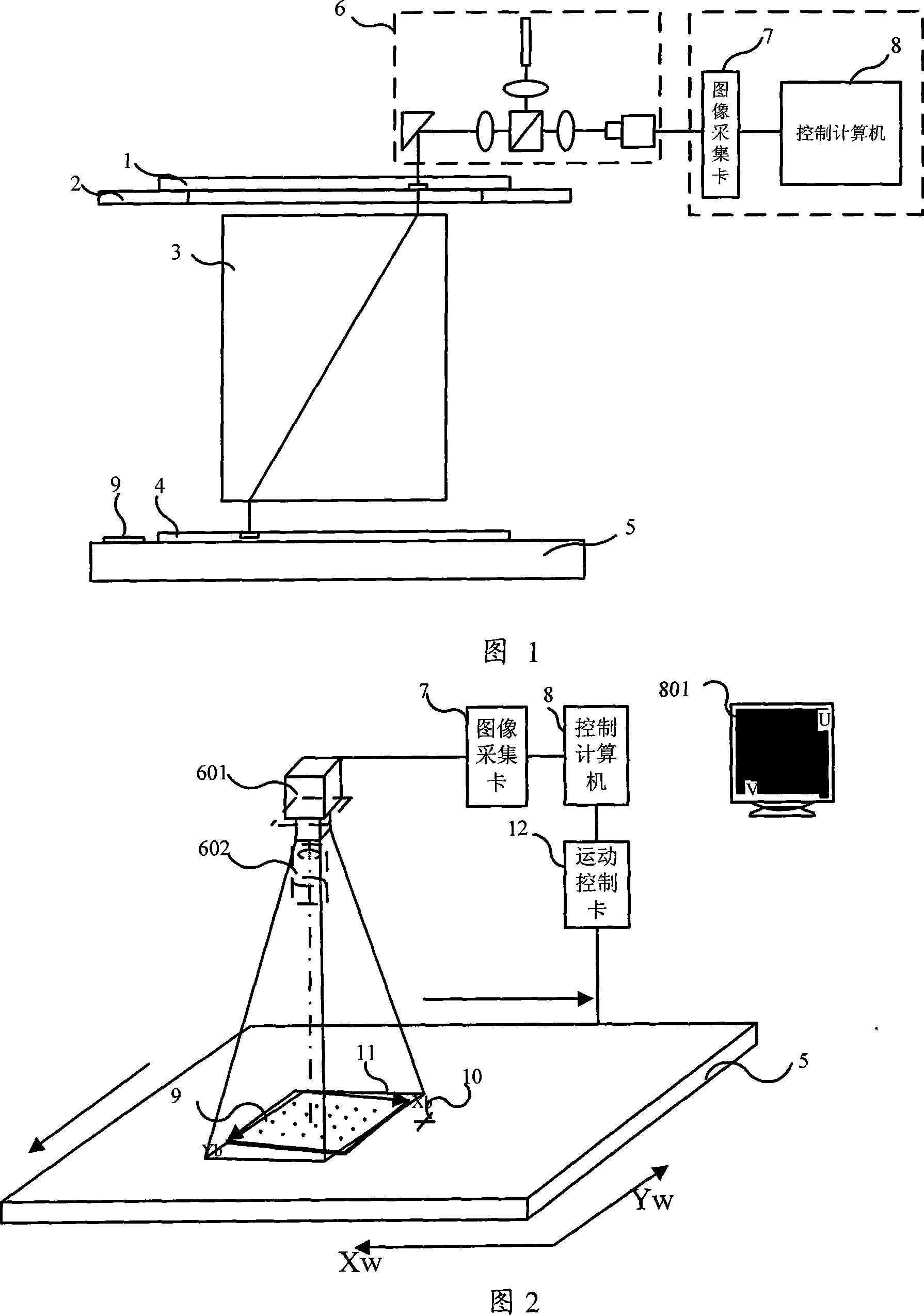
[0020] Please refer to FIG. 1 for a schematic structural diagram of a machine vision alignment system in a stepper lithography machine. The alignment system of the stepper lithography machine includes: a reticle 1 , a mask carrier 2 , a projection objective 3 , a silicon wafer 4 , a silicon wafer carrier 5 , an imaging system 6 , an image acquisition card 7 and a control computer 8 . A calibration plate 9 is installed on the silicon wafer carrier platform 5 , and images of marks on the mask plate 1 and silicon wafer 4 are obtained through the imaging system 6 , and the digital images are collected and transmitted to the control computer 8 through the image acquisition 7 . Through the pattern recognition technology, the position of the image coordinate system of the mark is respectively acquired and converted into the coordinate system of the mask carrier 2 and the coordinate system of the silicon wafer carrier 5 . Automatic alignment is achieved through the coordinate position...


PUM


Abstract

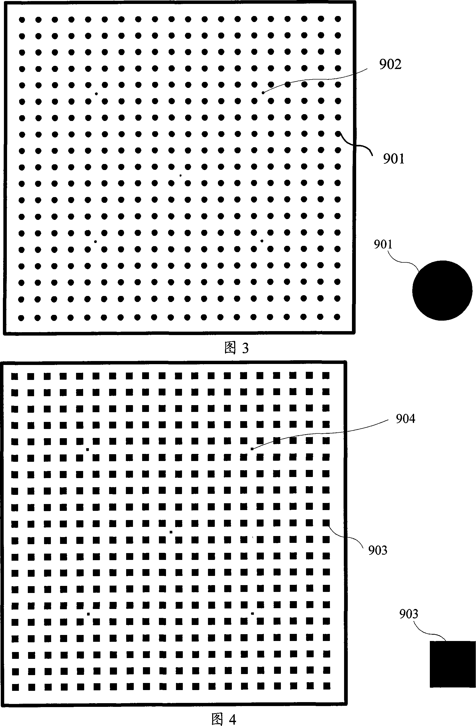
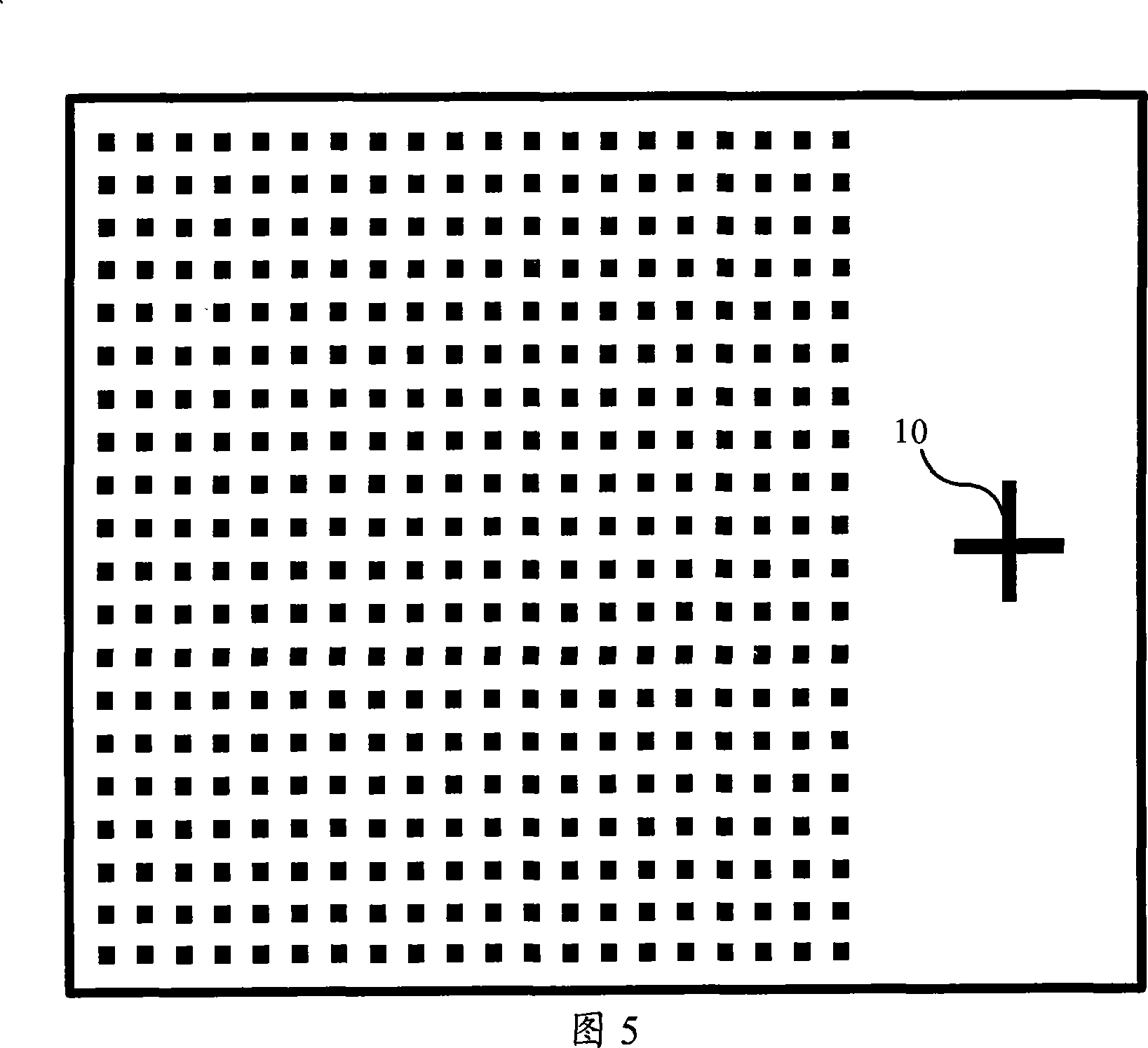
The invention provides a calibrating device and method used for the aligning system of a stepping photoetching machine. The aligning system consists of a locating platform and a control computer. The calibrating device consists of a calibrating board and a calibrating marker. The calibrating board is provided with the common calibrated points distributed in a matrix way on the calibrating board and locating calibrated points distributed oddly and evenly on the calibrating board. The calibrating marker is positioned in the range of the calibrating board without calibrated points or on the locating platform. The calibrating method can realize an alignment of the aligning system by establishing a relationship between the coordinate system of the calibrating board and the image coordinate on the control computer and establishing a relationship between the coordinate system of the calibrating board and the external coordinate system of the locating platform to establish a relationship between the image coordinate system on the control computer and the external coordinate system of the locating platform. The calibrating device and method of the invention is compatible with the aligning system of the stepping photoetching machine, and has higher aligning precision and reliability.

Description

technical field [0001] The invention relates to the field of an alignment system of a stepper lithography machine, in particular to a calibration device and a calibration method for an automatic alignment system of a stepper lithography machine. Background technique [0002] The function of the stepper is to project the circuit pattern drawn on the reticle onto the surface of the exposure object such as a silicon wafer coated with a photosensitive material by means of optical projection. Then, the pattern transfer between the mask plate and the exposure object is realized through etching and other processes. Since chips are composed of multiple layers of circuits, integrated circuit chips usually require multiple exposures to complete. To ensure precise positional relationship between different circuit layers, precise alignment between mask and exposure object must be achieved during projection exposure. [0003] In the projection exposure system of the current stepper lit...

Claims


Application Information

Patent Timeline
Patent Type & Authority Applications(China)
IPC IPC(8): G03F7/20G06T7/00
Inventor 谢威徐兵周金明蔡巍
Owner SHANGHAI MICRO ELECTRONICS EQUIP (GRP) CO LTD
Learn More