Electromagnetic shielding for high field MRI coils

A coil and radio frequency coil technology, applied in the measurement of magnetic variables, measurement devices, instruments, etc., can solve the problems of radiation loss, electromagnetic coupling and the reduction of the effectiveness of the radiation coil, and achieve the effect of reducing radiation loss, reducing SAR, and increasing SNR

Active Publication Date: 2008-04-30
KONINKLIJKE PHILIPS ELECTRONICS NV
View PDF0 Cites 7 Cited by
  • Summary
  • Abstract
  • Description
  • Claims
  • Application Information

AI Technical Summary

Problems solved by technology

Existing RF shielding becomes less effective at reducing electromagnetic coupling and radiating coil losses as the magnetic field and resonant frequency increase, for ex

Method used


Image

  • Electromagnetic shielding for high field MRI coils
  • Electromagnetic shielding for high field MRI coils
  • Electromagnetic shielding for high field MRI coils

Examples


Embodiment Construction

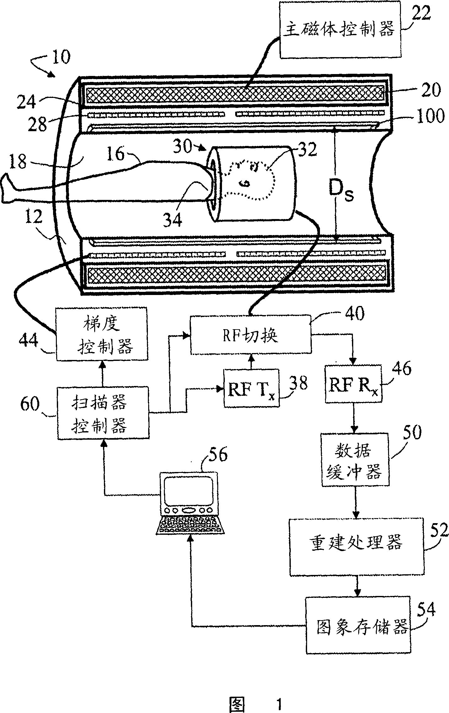
[0028] Referring to FIG. 1 , a magnetic resonance imaging scanner 10 includes a scanner housing 12 in which is at least partially disposed a patient or other imaging subject 16 . Cosmetic bore liner 18 of scanner housing 12 optionally delineates a cylindrical bore or opening of scanner housing 12 in which imaging subject 16 is disposed. A main magnet 20 disposed in the scanner housing 12 is controlled by a main magnet controller 22 to generate a main magnetic field B in the imaged subject 16 0 . Typically, the main magnet 20 is a durable superconducting permanent magnet surrounded by cryoshrouding 24 . The main magnet 20 generates a main magnetic field, typically about 3 Tesla or higher. In some embodiments, the main magnetic field is about 7 Tesla.

[0029] Magnetic field gradient coils 28 are arranged in or on housing 12 to superimpose selected magnetic field gradients on the main magnetic field. Typically, the magnetic field gradient coils include coils for generating t...


PUM


Abstract

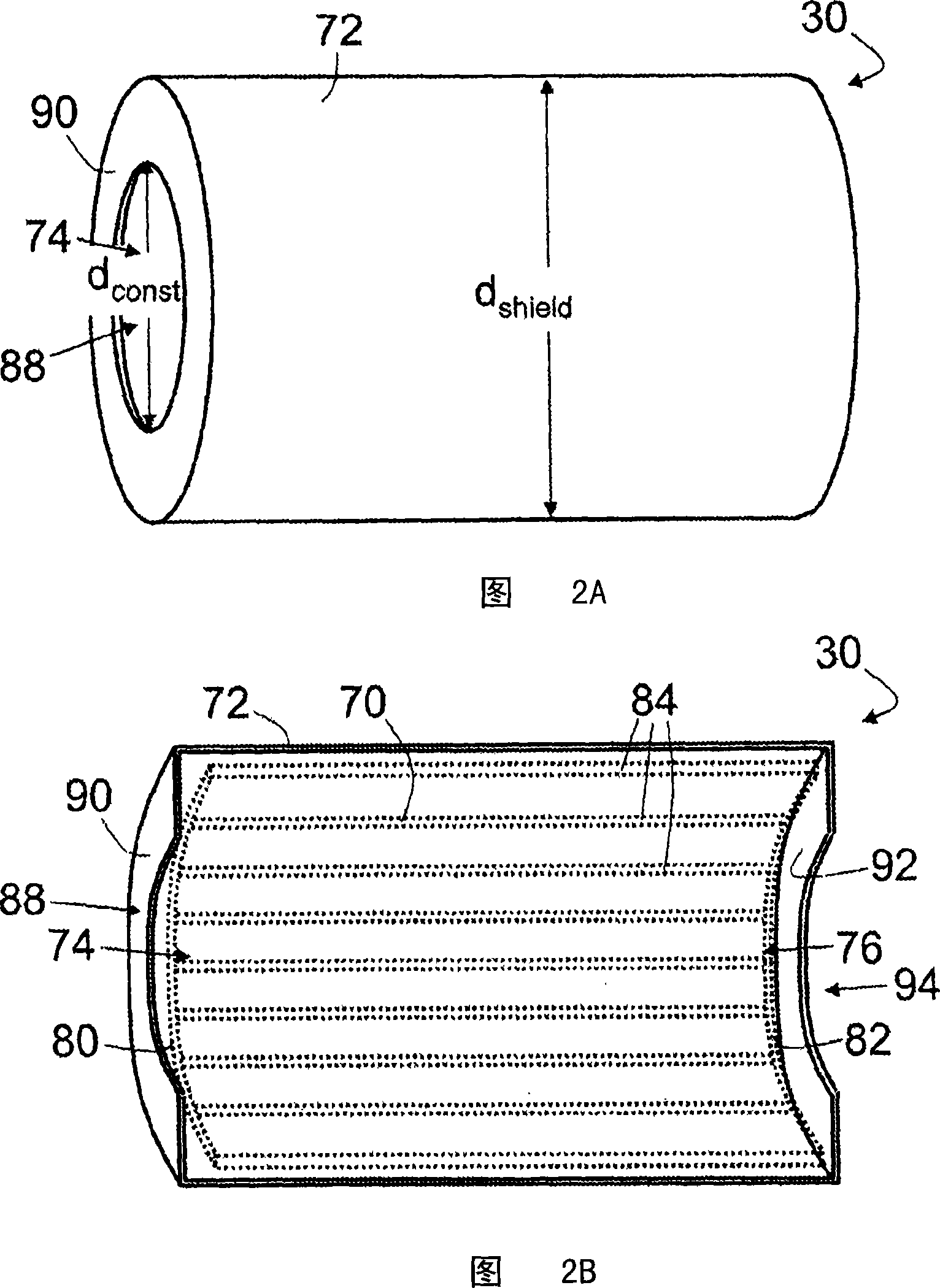
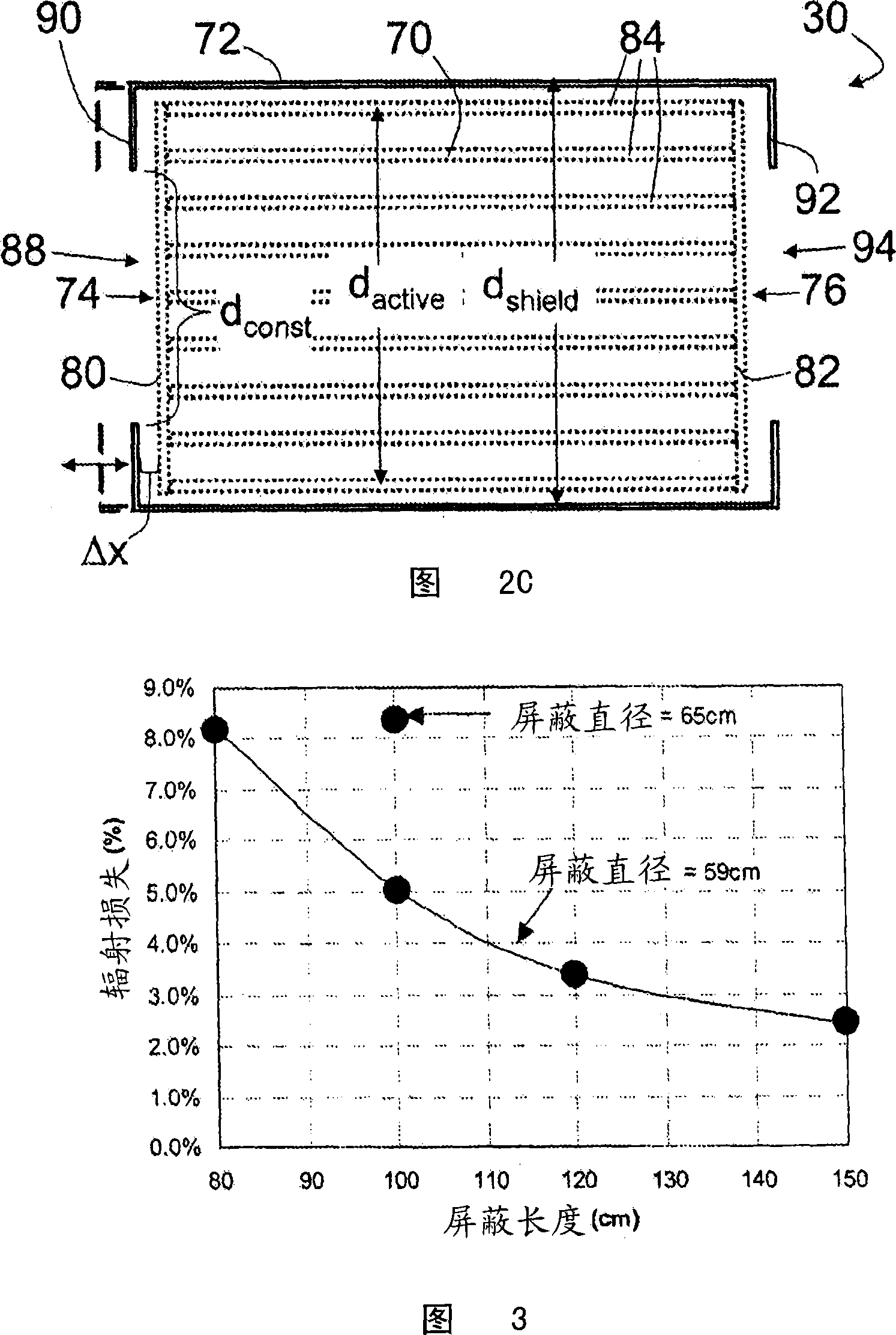
A radio frequency coil for magnetic resonance imaging includes an active coil member (70, 701, 170, 270) that defines an imaging volume. The active coil member has a first open end (74) with a first cross-sectional dimension (dactive). A shield coil member (72, 721, 722, 723, 724, 725, 172, 1722, 272) substantially surrounds the active coil member. The shield coil member has a constricted open end (88) arranged proximate to the first open end of the active coil member with a constricted cross-sectional dimension (dconst) that is less than the cross-sectional dimension (dShieid) of the shield coil member. In some embodiments, the radio frequency coil further includes an outer shield coil member (100) that is substantially larger than the shield coil member (72, 721, 722, 723, 724, 725, 172, 1722, 272), and surrounds both the active coil member and the shield coil member.

Description

technical field [0001] The following relates to the field of magnetic resonance imaging. It finds particular application in high field magnetic resonance imaging (MRI), such as imaging at about 3 Tesla or higher, and will be described with particular reference to it below. However, it can also be applied to magnetic resonance imaging, magnetic resonance spectroscopy, etc. performed at lower magnetic fields. Background technique [0002] In magnetic resonance imaging, an imaging subject is placed in a temporally constant main magnetic field and subjected to radio frequency (RF) excitation pulses to generate nuclear magnetic resonance in the imaging subject. Magnetic field gradients are superimposed on the main magnetic field to spatially encode the magnetic resonance. The spatially encoded magnetic resonance is read out and reconstructed based on the spatial encoding to generate a magnetic resonance image. [0003] In magnetic resonance imaging, the signal-to-noise ratio (...

Claims


Application Information

Patent Timeline
IPC IPC(8): G01R33/422
CPCG01R33/3628G01R33/422
Inventor C·G·卢斯勒K·卢德克M·A·莫里克Z·翟G·D·德米斯特
Owner KONINKLIJKE PHILIPS ELECTRONICS NV
Why Eureka
Try Eureka