Electric machine

A rotor and fan technology, applied in the field of automotive fan units, can solve the problem that the positioning of air ducts and similar components cannot completely eliminate functional defects, and achieve the effects of avoiding motor failure, high service life, and small structural space

Inactive Publication Date: 2008-04-30
BROSE FAHRZEUGTEILE GMBH & CO KG HALLSTADT (DE)
View PDF1 Cites 21 Cited by
  • Summary
  • Abstract
  • Description
  • Claims
  • Application Information

AI Technical Summary

Problems solved by technology

The disadvantage of these known solutions is that they always rely on structural or functional constraints for the positioning of air ducts and the like and functional disadvantages cannot be completely ruled out here

Method used


Image

  • Electric machine
  • Electric machine
  • Electric machine

Examples


Embodiment Construction

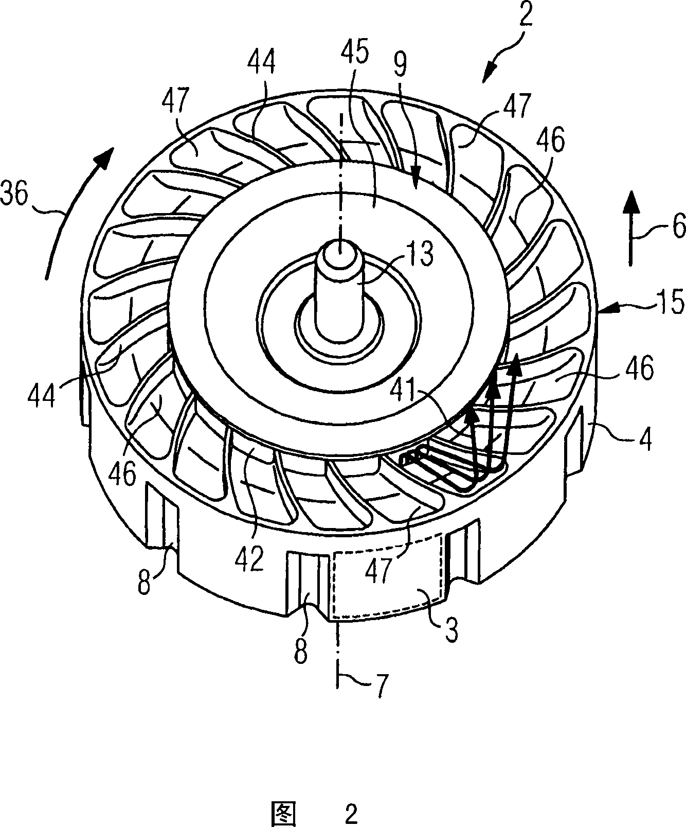
[0030] FIG. 1 shows a perspective view of the rear side 1 of a rotor 2 according to the invention. The rotor 2 is a permanently excited inner rotor of a brushless electromagnetic DC motor which is used in motor vehicles in particular as a radiator fan motor.

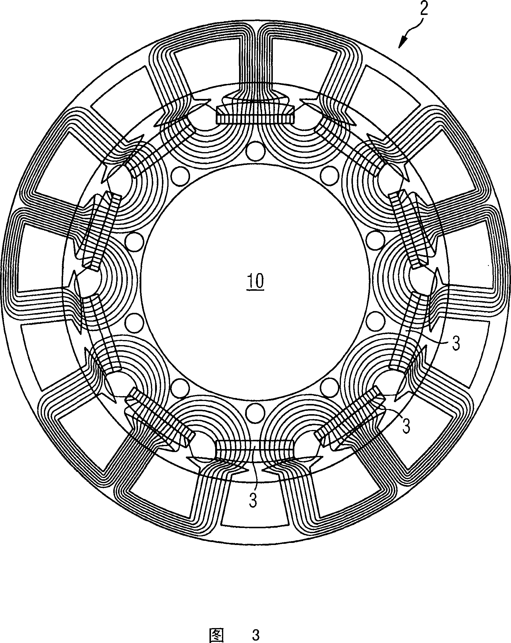
[0031] The rotor 2 has so-called pocket magnets 3 (indicated by dashed lines in FIG. 2 ). The magnets 3 are arranged at a distance from one another on the circumference 4 of the rotor 2 . The magnet 3 is for example a rare earth magnet based on NdFeB (Neodymium Iron Boron). Said magnets 3 are in pockets 5 molded in iron on the circumference 4 of the rotor. In order to prevent oxidation, the magnet 3 is extruded and encapsulated with plastic material. The advantage of such a magnet embedded in iron is that it is less prone to demagnetization even at high currents. Between the pockets 5 receiving the magnets 3 , on the circumference 4 of the rotor 2 , grooves 8 arranged in the axial direction 6 , ie parallel to the axi...


PUM


Abstract

The invention relates to an electric machine comprising a rotor and a stator as well as a method for cooling such a machine. In order to improve cooling of an electric machine, the inventive electric machine (18) comprises a rotor (2) that is excited by permanent magnets, a stator (38), magnets (3) which are arranged along the circumferential line of the rotor (2) in such a way that a magnetically non-effective zone (10) is created around the center of the rotor (2), at least one opening (11) in the magnetically non-effective zone (10) of the rotor (2) in order to embody an air flow path (41) through the rotor (2), said opening (11) extending substantially in an axial direction, and a fan (15, 56, 58, 59) which moves along with the rotor (2) and is used for embodying an air flow through the opening (11) of the rotor (2).

Description

technical field [0001] The invention relates to an electric machine with a rotor and a stator. Among other things, the invention also relates to a fan unit, in particular for a motor vehicle. Background technique [0002] An electric machine with a rotor and a stator can be used on the one hand as a generator for generating electric current and on the other hand as a drive motor. For the stable operation of such motors, it is necessary to avoid overheating which would lead to a shortened service life of the motor or complete failure of the motor. In this case, especially the electronic components of modern electrical machines are thermally critical components and thus increase the cooling requirements. In order to dissipate the resulting power loss and adjust the overall thermal budget of such an electric machine, numerous solutions are known, for example in which special heat sinks are used or water cooling is used. Furthermore, the use of an additional fan arranged on t...

Claims


Application Information

Patent Timeline
Patent Type & Authority Applications(China)
IPC IPC(8): H02K9/06H02K1/30H02K1/32H02K11/04
CPCH02K1/32H02K11/0073H02K5/20H02K9/06H02K15/03H02K1/276H02K11/33H02K5/207H02K1/30
Inventor P·德菲利皮斯H·雷德尔伯格D·克默H·舒尔茨
Owner BROSE FAHRZEUGTEILE GMBH & CO KG HALLSTADT (DE)
Why Eureka
Try Eureka