
Automatic deformation mechanical figure toy

A robot and toy technology, applied in the field of automatic deformation robot toys, can solve the problems of automatic deformation, no space to install driving moving parts, complex deformation mechanism, etc., and achieve the effect of simple deformation process, simple structure and space saving

Inactive Publication Date: 2008-05-07
肖伟
View PDF1 Cites 10 Cited by
  • Summary
  • Abstract
  • Description
  • Claims
  • Application Information

AI Technical Summary

Problems solved by technology

This robot toy includes: multiple articulated mechanism parts that can be assembled and disassembled to form robots of different shapes, but it must be deformed by hand
[0003] Traditional transforming robot toys cannot transform automatically. The reason is that the transforming mechanism is so complicated that there is no space to install the driving device that drives the moving parts to move as required.

Method used


Image

  • Automatic deformation mechanical figure toy
  • Automatic deformation mechanical figure toy
  • Automatic deformation mechanical figure toy

Examples


Embodiment 1

[0024] Realization of various functions:

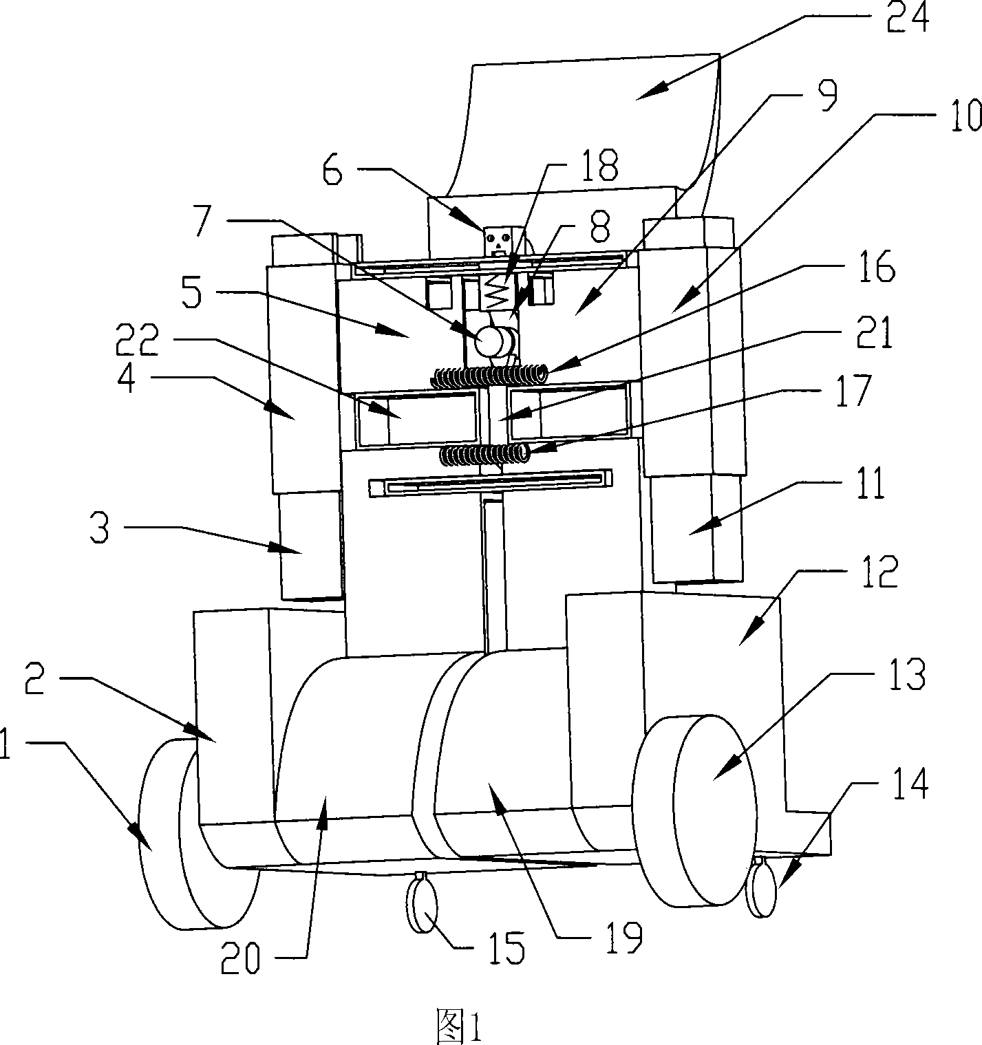
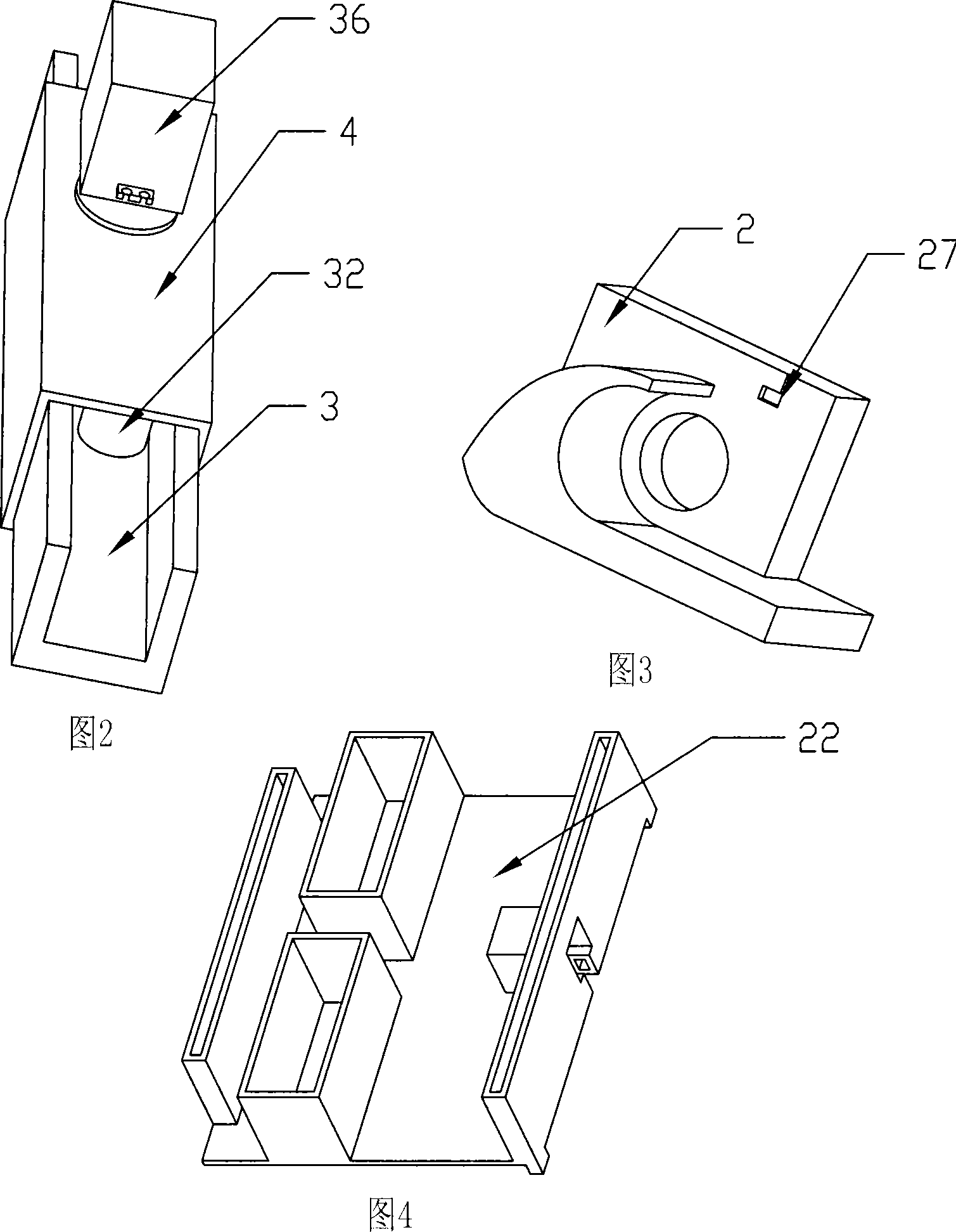
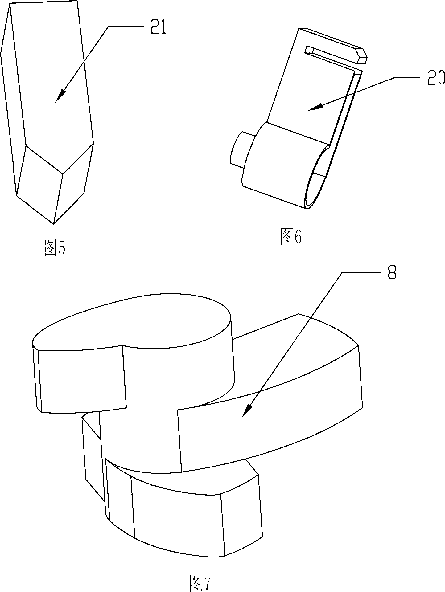
[0025] a. Extension and retraction of the head. The square hole on chest cavity 22 top shown in Figure 1 is the telescopic sliding hole of head 6, and head 6 can double as push rod, and whole head is elongated cuboid shape, can slide in the square hole on chest cavity 22 tops. One end of spring 18 links to each other with head 6, and the other end links to each other with chest cavity 22, and head 6 retracts chest cavity 22 under the effect of spring 18 like this when composite cam 8 rotates from high point to low point.

[0026] b. Extension and retraction of hands. The square cavity formed by the top of the chest cavity 22 shown in Figure 1 and the chest cavity loam cake provides a sliding cavity for the slide arm 9 in the left chest cavity and the slide arm 5 in the right chest cavity. The sliding arm 5 in the right thoracic cavity is connected. When the composite cam 8 rotates through the corresponding angle, the sliding arm 9 i...

Embodiment 2

[0042] This embodiment is only different from Embodiment 1 in four places. The first place is, in the present embodiment, a screw nut is used at the upper arm, that is, the motor 29 is fixed on the left upper arm 10, the left lower arm 11 is fixedly connected with the nut 30, and the lead screw 31 is connected with the rotor of the motor 29 to realize the left lower arm 11. Slide along the lumen of left upper arm 10 . The second is that the locking mechanism at the foot adopts a spring-returning electromagnet, and the functions in Embodiment 1 are realized by energizing and disconnecting the electromagnet. The third place is to open a small slit at an appropriate position on the left leg 28 and when the electromagnet 32 ​​is de-energized, the stopper 34 is inserted into the small slit on the left leg 28 under the action of the spring 33, so that the robot body is convenient for the feet to be relatively fixed. , thus locking the robot. The fourth point is that in this embodi...


PUM


Abstract

The invention discloses an automatic distortion robot toy, which automatically distorts between an automobile and a robot and comprises a thoracic cavity, four limbs which can move left and right in the thoracic cavity, a head part which can extend and retract to the thoracic cavity, a compound cam realizing the stretching of the head part and the four limbs, feet, and a plurality of motors. A control device controls each motor to regularly revolve the corresponding angle to complete that the robot is changed into the automobile, and the automobile is changed into the robot. No matter what condition the robot is in, the robot can freely walk back and forth, and left and right under the remote control or the voice control.

Description

technical field [0001] The invention belongs to the technical field of robot toys, in particular to a robot toy that can automatically transform between a robot and a car. Background technique [0002] Transformable robot toys are more interesting than other single-body toys. However, the traditional transforming robot toys are manually transformed, that is, the movable mechanism on the robot can only be rotated manually, and some parts even have to be removed from the robot and replaced with other parts to become certain shape. The deformation process is extremely cumbersome, which greatly reduces the interest of the deformed robot. China CN1517138 published on August 4th, 2004 discloses a kind of artificial intelligence robot toy, which is easily assembled and controlled into different shapes by using a joint motor. The robot toy includes: multiple joint mechanism parts that can be assembled and disassembled to form robots of different shapes, but it must be deformed by...

Claims


Application Information

Patent Timeline
Patent Type & Authority Applications(China)
IPC IPC(8): A63H3/04A63H3/36A63H3/46A63H11/18A63H17/00A63H17/26A63H29/22
Inventor 肖伟
Owner 肖伟
Learn More